Collapsible ballistic shield

Inactive Publication Date: 2004-10-26
PATRIOT3
View PDF17 Cites 124 Cited by
  • Summary
  • Abstract
  • Description
  • Claims
  • Application Information

AI Technical Summary

Problems solved by technology

This first responder may not have access to a needed ballistic shield, because the space requirements of a unitary,

Method used


Image

  • Collapsible ballistic shield
  • Collapsible ballistic shield
  • Collapsible ballistic shield

Examples


Embodiment Construction

refers to the accompanying drawings. The same reference numbers may be used in different drawings to identify the same or similar elements. Also, the following detailed description does not limit the invention. Instead, the scope of the invention is defined by the appended claims and equivalents.

Exemplary Three Portion Shield

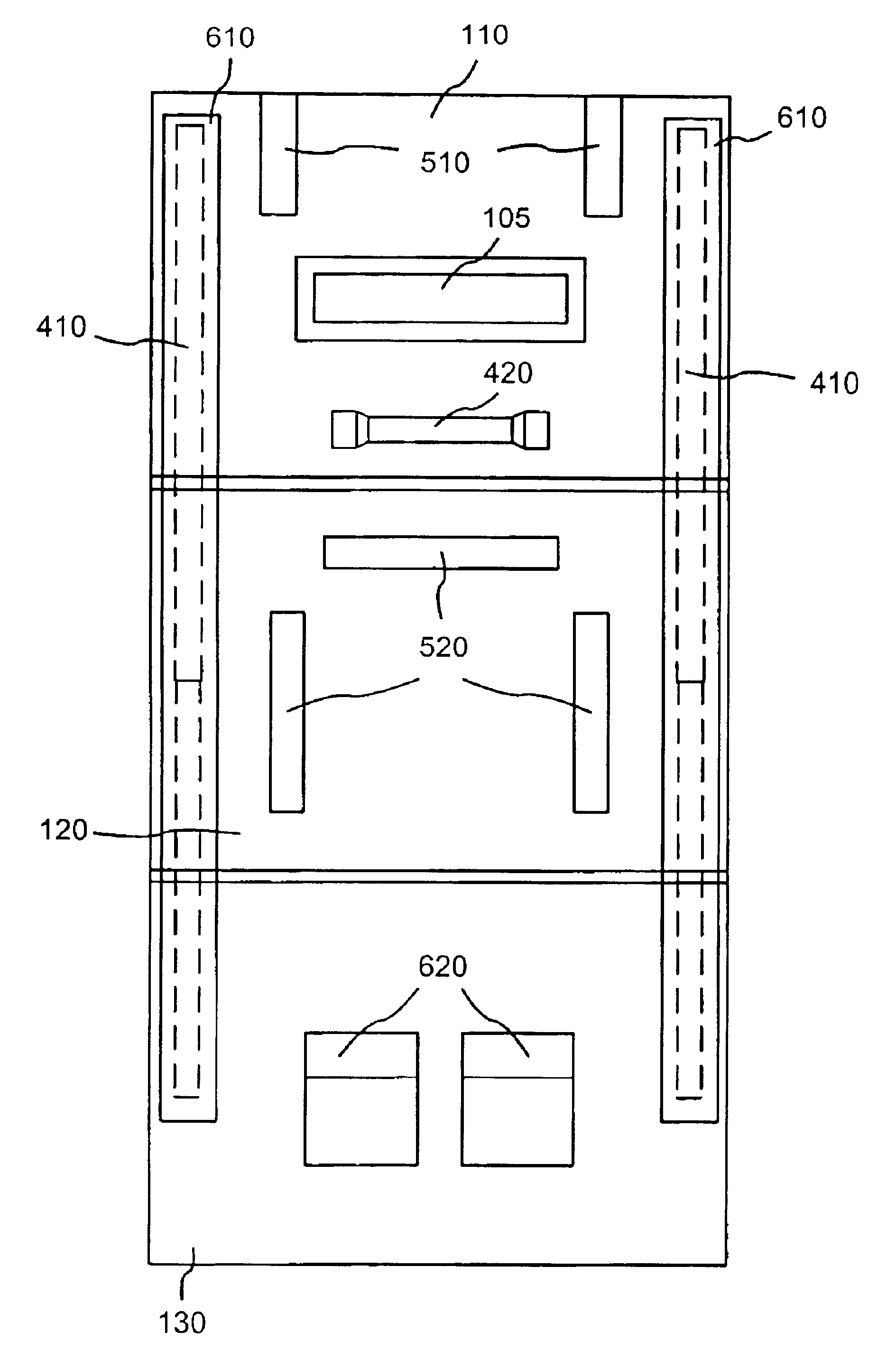
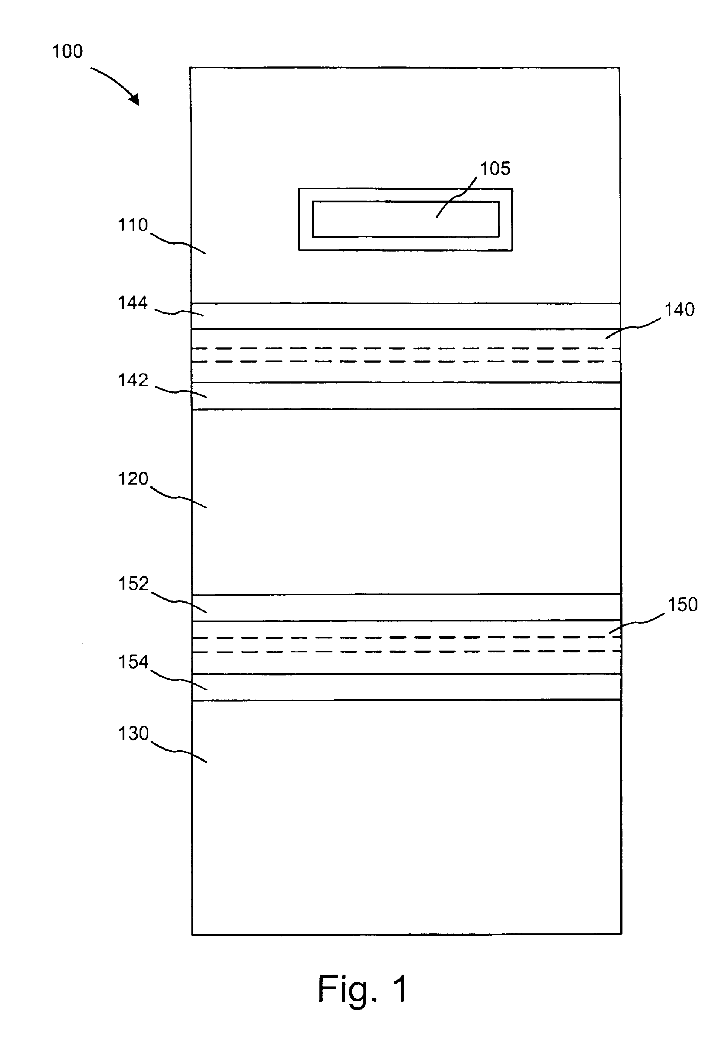
FIG. 1 is a diagram illustrating a front view of an exemplary ballistic shield 100 according to an implementation consistent with the present invention. Shield 100 may include a top portion 110, a middle portion 120, a bottom portion 130, a top overlapping panel 140, and a bottom overlapping panel 150. Top portion 110, middle portion 120, and bottom portion 130 may be flexibly connected so that these three portions 110-130 may fold (e.g., in a "Z" manner) to overlap one another. The flexible connections between top portion 110 and middle portion 120, and between middle portion 120 and bottom portion 130, are illustrated as dashed lines in FIG. 1.

Top portion 110 ...


PUM


Abstract

A ballistic shield may include a first ballistic plate that includes a ballistic material. A second ballistic plate may also include the ballistic material. The second ballistic plate may be connected to a side of the first ballistic plate so that the first ballistic plate and the second ballistic plate may fold together to substantially overlap. A gap may exist between the first ballistic plate and the second ballistic plate when not folded together. An overlapping ballistic section may include the ballistic material. The overlapping ballistic section may be connected to the first ballistic plate and/or the second ballistic plate so that the overlapping ballistic section covers the gap between the first ballistic plate and the second ballistic plate.

Description

1. Field of the InventionThe present invention relates generally to portable shields, and more particularly, to portable ballistic shields.2. Description of Related ArtPortable shields may be employed for personal protection by law enforcement, military, security, and other personnel. Such portable shields may be typically carried and employed by one person, although the shield may be placed to shelter additional persons behind it.Ballistic shields are one type of portable shield that are designed to provide additional protection against ballistic projectiles (e.g., bullets fired from a gun). As used herein, a "ballistic" shield or material may be defined as having the property of stopping, or severely retarding the progress of, a projectile such as a bullet. As used herein, "ballistic" may be used interchangeably with "bulletproof," though ballistic material may not be completely impenetrable to all types of bullets and other projectiles under all situations.Ballistic shields, alth...

Claims


Application Information

Patent Timeline
IPC IPC(8): F41H5/08F41H5/00
CPCF41H5/08
Inventor FUQUA, CHARLES
Owner PATRIOT3
Why Eureka
Try Eureka