
Vented protective garment

Inactive Publication Date: 2005-01-25
LION GROUP
View PDF23 Cites 16 Cited by
  • Summary
  • Abstract
  • Description
  • Claims
  • Application Information

AI Technical Summary

Problems solved by technology

However, although the moisture barrier may be generally permeable to moisture vapor to allow moisture vapor to pass therethrough, moisture vapor may still remain trapped inside the garment.

Method used


Image

  • Vented protective garment
  • Vented protective garment
  • Vented protective garment

Examples


Embodiment Construction

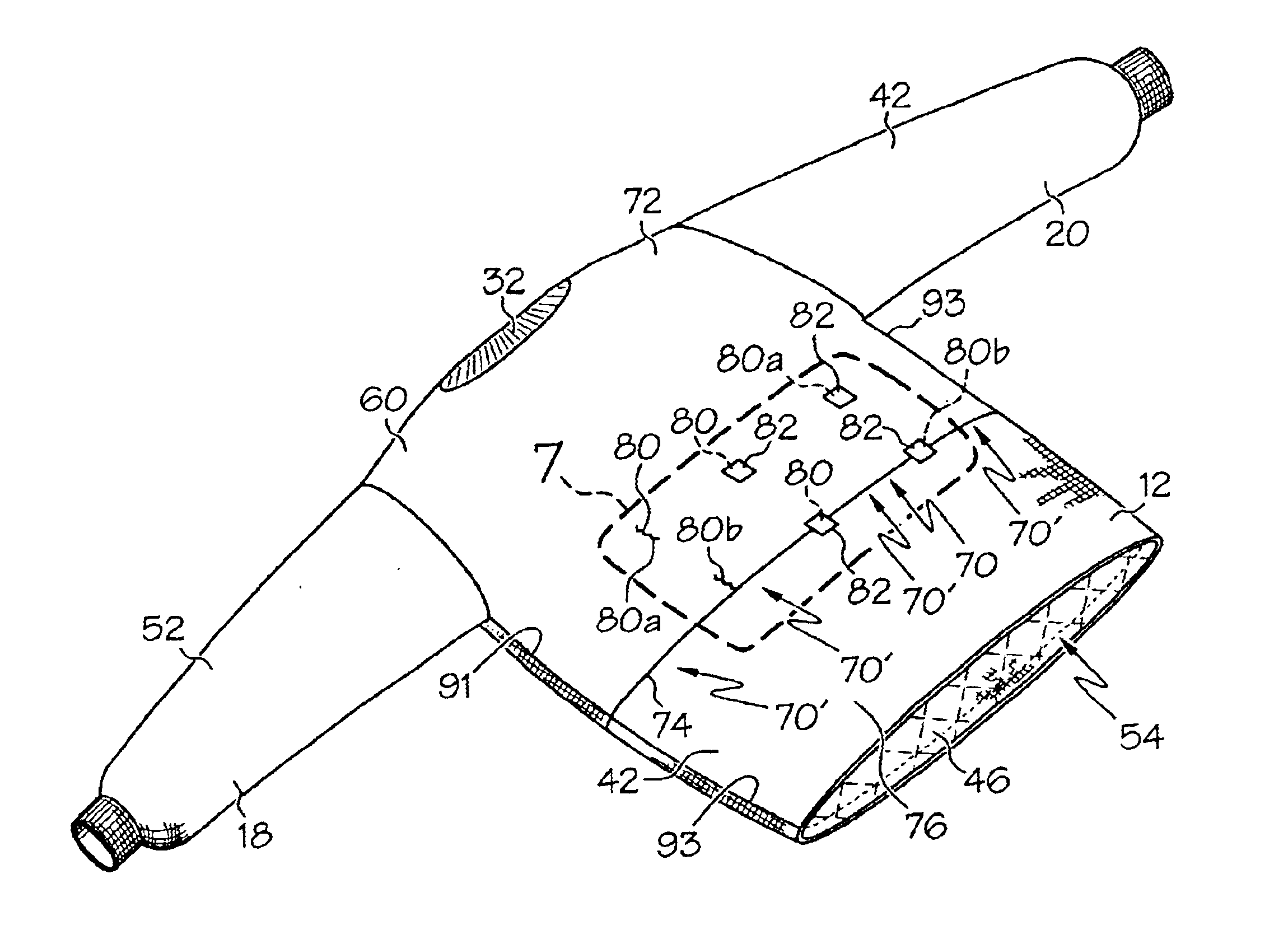
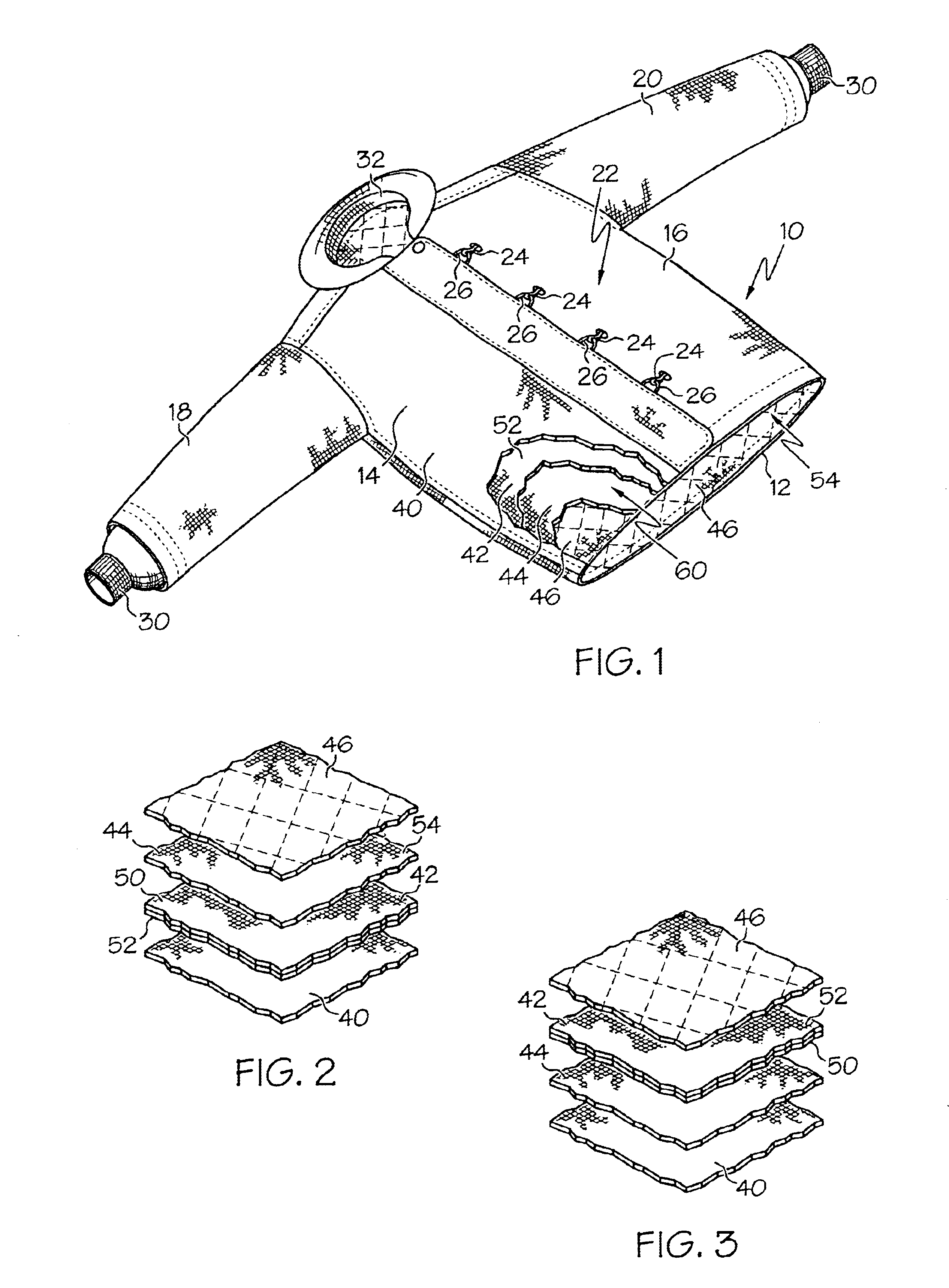
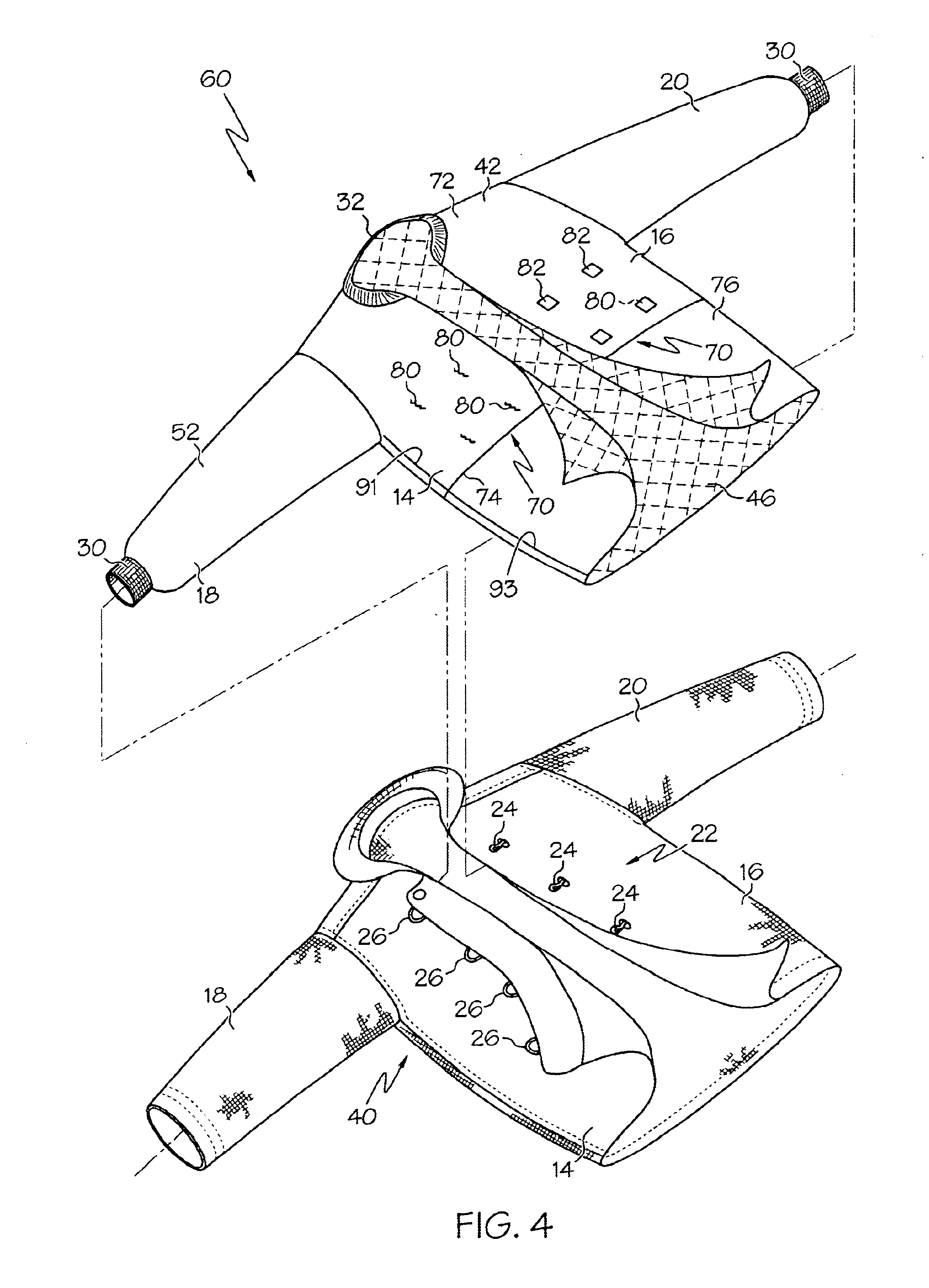
FIG. 1 illustrates a protective or hazardous duty garment in the form of a firefighter turnout coat, generally designated 10. The coat 10 may have aback panel 12, a left 14 and a right 16 front panel coupled to the back panel 12, and a pair of sleeves 18, 20 coupled to and extending generally outwardly from the back panel 12 and front panels 14, 16. The front panels 14, 16 may be permanently attached to the back panel 12 and sleeves 18, 20. The panels 14, 16 may be releasably attachable together by a fastening component, generally designated 22. In the illustrated embodiment, the fastening component 22 includes hooks 24 on the panel 16 which can cooperate with clasps 26 on the panel 14 to selectively close the coat 10. However, the fastening component 22 may include nearly any other fastener or fastening system, including but not limited to slide fastener components, snaps, zippers, buttons, hook and loop fastening systems, and the like.

The coat 10 may include a pair of knit wristle...


PUM


Abstract

A protective garment including a generally continuous outer shell and a moisture barrier located generally inside of the outer shell such that when the garment is worn, the moisture barrier is located generally between the outer shell and a wearer of the garment. The moisture barrier includes at least one vent such that at least part of the air located inside the moisture barrier can be vented outside of the moisture barrier.

Description

BACKGROUNDThe present invention relates to garments and, more particularly, to protective garments having a vent such as a vented moisture barrier.Protective or hazardous duty garments and garment sets are widely used in various industries to protect the wearer from various hazardous conditions, such as heat, smoke, cold, sharp objects, chemicals, liquids, fumes and the like. Each protective garment may include an outer shell layer, a thermal barrier or thermal liner located inside the outer shell, and a moisture barrier located inside the outer shell. The moisture barrier may be semi-permeable such that the moisture barrier is generally liquid impermeable and generally moisture vapor permeable.The moisture barrier may be located inside the outer shell to block moisture from the ambient environment from passing through the garment, while allowing moisture vapor inside the garment to pass through the moisture barrier. However, although the moisture barrier may be generally permeable ...

Claims


Application Information

Patent Timeline
IPC IPC(8): A62B17/00
CPCA41D13/00A62B17/003A41D27/28
Inventor ALDRIDGE, DONALDCURTIS, NICHOLAS J.OAKLEY, HAROLD
Owner LION GROUP
Features
  • Generate Ideas
  • Intellectual Property
  • Life Sciences
  • Materials
  • Tech Scout
  • Unparalleled Data Quality
  • Higher Quality Content
  • 60% Fewer Hallucinations
Learn More