Caster lock indicator

a technology of lock indicator and caster, which is applied in the direction of wheel mounting apparatus, brake system, manufacturing tools, etc., can solve the problems of complex structure of known caster lock device and no appropriate lock indicator has been proposed to date for such casters that are equipped with lock devi

Inactive Publication Date: 2005-02-15
SUGATSUNE IND CO LTD
View PDF10 Cites 25 Cited by
  • Summary
  • Abstract
  • Description
  • Claims
  • Application Information

AI Technical Summary

Benefits of technology

In the first aspect of the invention, the above first object is achieved by providing a caster lock indicator to be used for a caster comprising a wheel fitted to a leg member rigidly or rotatably secured to a fitting section, said caster having a stopper lever rotatably fitted to said leg member by way of a lever support member and adapted to be rotated in order to turn a stopper spring also fitted to said leg member by way of a spring support member, thereby causing the fitting section side part of the stopper spring to be held relative to said fitting section so as to lock the leg member against any rotary motion and / or causing the stopper lever side part of the stopper spring to abut the wheel so as to lock the wheel against any swiveling motion, said lock indicator having a lock indicator plate, characterized in that the part for indicating the unlocked state of the lock indicator surface of the lock indicator plate slidably contained in a guide space of the stopper lever is visually recognizable through the indicator window when the stopper lever is in the unlocked state, whereas the part for indicating the locked state of the lock indicator surface of the lock indicator plate located adjacent to the part for indicating the unlocked state is visually recognizable through the indicator window instead of said part for indicating the unlocked state when the stopper lever is rotated to lock the leg member and / or the wheel as the lock indicator plate anchored to a stopper lever side part of the stopper spring supported by the spring support member arranged at a position different from said lever support member is made to returnably slide in said guide space relative to the stopper lever.
In the second aspect of the invention, the above second object is achieved by providing a caster lock indicator to be used for a caster comprising a wheel fitted to a leg member rigidly or rotatably secured to a fitting section, characterized in that said stopper spring is fitted to an upper part of the leg lateral wall sections of said leg member by way of a spring support member so as to be turned freely, said stopper spring having a stopper lever side part extending at the side opposite to the fitting section side thereof, a stopper lever is also rotatably fitted to the leg member by way of a lever support member arranged at a position more remote from the fitting section than the spring support member, said stopper lever having an indicator window, a projecting pusher section formed near the lever support member and a guide space containing a lock indicator plate so as to make the latter slidable, the free end side of said stopper lever side part being releasably engaged with an engaging section formed at the lever support member side of the lock indicator plate, so that the part for indicating the unlocked state of the lock indicator surface of the lock indicator plate slidably and releasably anchored to the stopper lever is visually recognizable through the indicator window when the caster is in the unlocked state, whereas the part for indicating the locked state of the lock indicator surface of the lock indicator plate located adjacent to the part for indicating the unlocked state is visually recognizable through the indicator window instead of said part for indicating the unlocked state when the stopper lever is operated from the locked state of the caster in order to rotate it around the lever support member, thereby causing said projecting pusher section to push and resiliently deform said stopper lever side part so as to lock the leg member against any rotary motion by making the fitting section side of the stopper ring to be engaged with the fitting section and / or lock the wheel against any swiveling motion by making the stopper lever side part of the stopper spring to be pushed against the wheel.
In the third aspect of the invention, the above third object is achieved by providing a caster lock indicator to be used for a caster comprising a wheel fitted to a leg member rigidly or rotatably secured to a support of a fitting section, characterized in that a stopper spring is fitted to an upper part of the leg lateral wall sections of said leg member by way of a spring support member so as to be turned freely, said spring support member being running in parallel with the axle of the wheel and supporting said stopper spring substantially at the center thereof, said stopper spring having a fitting section side part extending at the support side thereof and having a biasing spring to be resiliently abutted against the leg member so as to operate as stopper for preventing the leg member from rotating and a stopper lever side part extending at the side opposite to the fitting section side thereof so as to operate as stopper for preventing the wheel from swiveling, a rotatable stopper lever being fitted to said leg member by way of a stopper lever support member arranged in parallel with the stopper spring support member at a position more remote from the fitting section than the stopper spring support member, said stopper lever having an indicator window, a projecting pusher section formed near said stopper lever support member and a guide space containing a lock indicator plate so as to make the latter slidable, the free end side of said stopper lever side part being releasably engaged with an engaging section formed at the lever support member side of the lock indicator plate, so that the part for indicating the unlocked state of the lock indicator surface of the lock indicator plate slidably and releasably anchored to the stopper lever is visually recognizable through the indicator window when the caster is in the unlocked state, whereas the part for indicating the locked state of the lock indicator surface of the lock indicator plate located adjacent to the part for indicating the unlocked state is visually recognizable through the indicator window instead of said part for indicating the unlocked state when the stopper lever is operated from the locked state of the caster in order to rotate it around the lever support member, thereby causing said projecting pusher section to push and resiliently deform said stopper lever side part so as to lock the leg member against any rotary motion by making the fitting section side of the stopper ring to be engaged with the fitting section and also lock the wheel against any swiveling motion by making the stopper lever side part of the stopper spring to be pushed against the wheel.

Problems solved by technology

However, known caster lock devices have a complex structure and typically involve the use of a gear and a gear rack and / or a locking recess formed in the wheel for locking the caster.
However, no appropriate lock indicators have been proposed to date for such casters that are equipped with a lock device.

Method used


Image

  • Caster lock indicator
  • Caster lock indicator
  • Caster lock indicator

Examples


Embodiment Construction

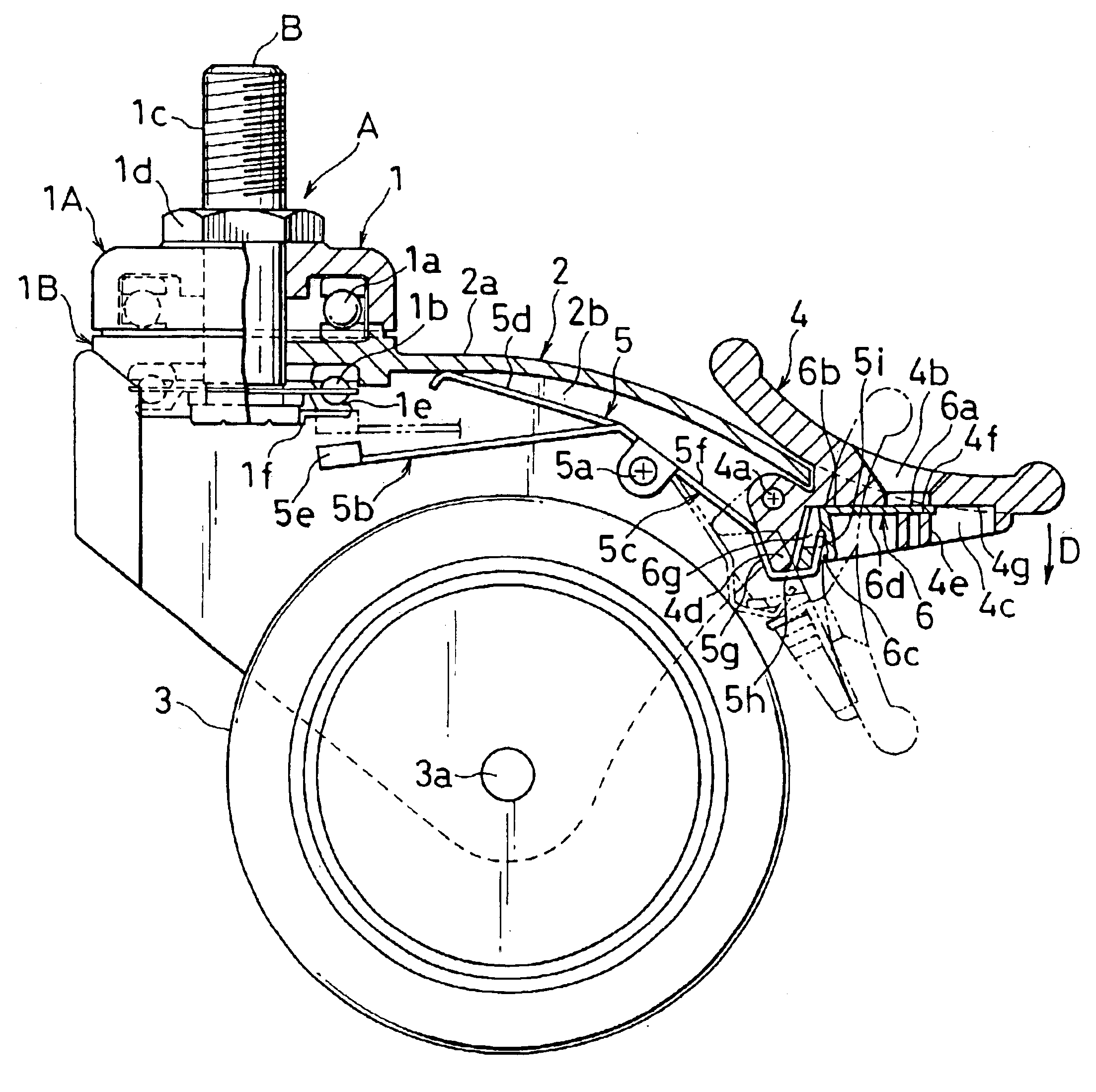
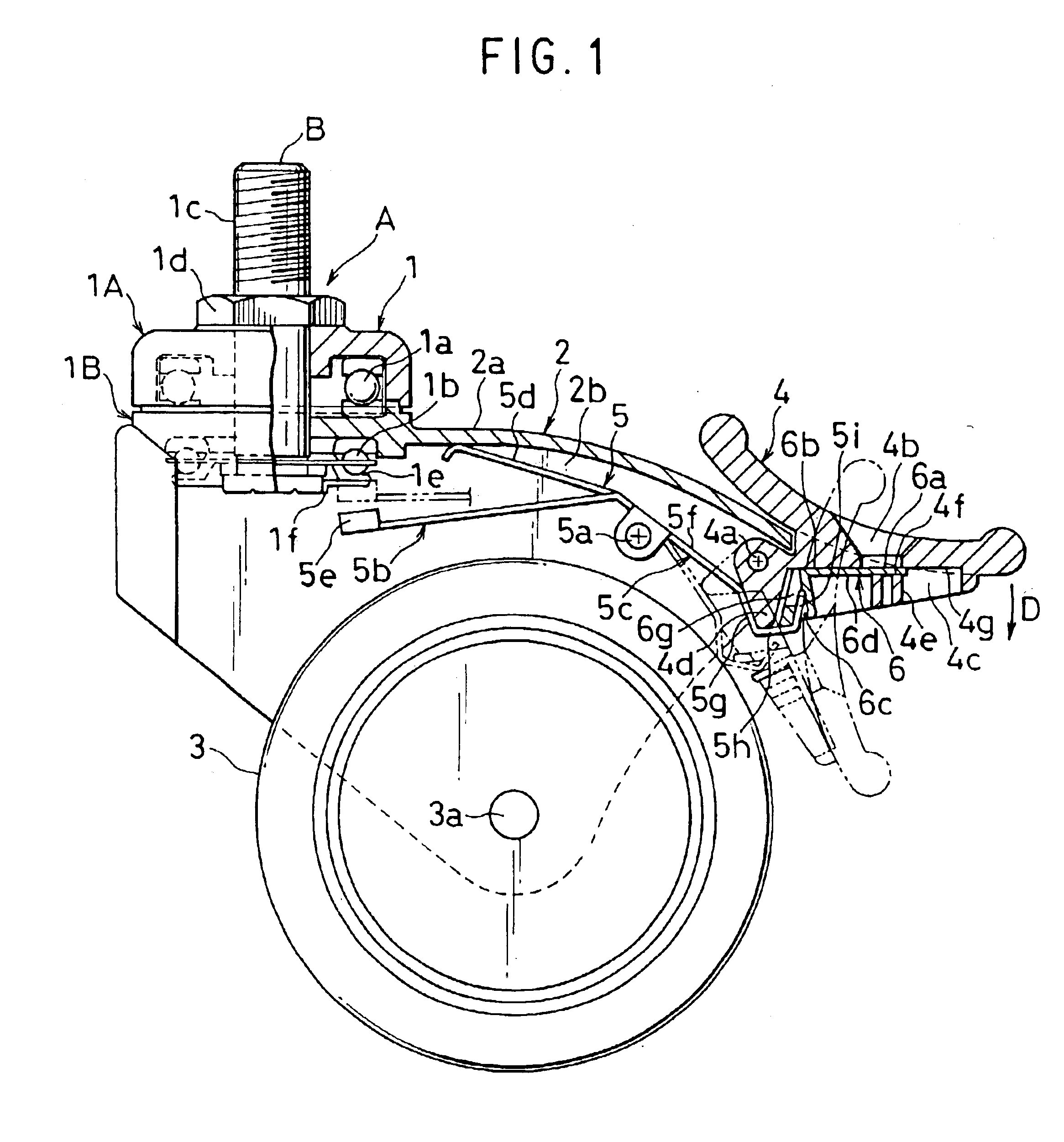
Now, an embodiment of the present invention will be described in detail by referring the accompanying drawings. Referring particularly to FIG. 1, caster A has a known configuration as described below. It comprises a fitting section B to be fitted to a chair, a table or the like. The fitting section B includes a support 1 realized by unifying an upper ball bearing section 1A containing upper balls 1a and a lower ball bearing section 1B containing lower balls 1b by means of a fitting bolt 1c and a nut 1d, although there are types that do not have such a support 1. The leg back plate section 2a of an inverted U-shaped leg member 2 is pinched between the upper ball bearing section 1A and the lower ball bearing section 1B in such a way that it can be rotated horizontally. In FIG. 1, reference symbol 2b denotes a pair of leg lateral plate sections bent and extended downward respectively from the front end and the rear end of the leg back plate section 2a. Wheel 3 is rotatably supported by...


PUM


Abstract

A caster lock indicator adapted to operate to indicate a locked state or an unlocked state of a caster. The caster lock indicator includes a stopper spring that operates in response to a rotary motion of a stopper lever when it is operated to unlock the caster. As the stopper lever is rotated around a lever support member, the stopper spring is turned about a stopper spring support member to lock the wheel against any swiveling motion. In the unlocked state, a lock indicator surface of a lock indicator plate can be visually recognizable through an indicator window of the stopper lever. When the caster is locked, the lock indicator plate is driven to slide so that the part for indicating the locked state of the lock indicator surface of the lock indicator plate comes to be visually recognizable through the indicator window.

Description

BACKGROUND OF THE INVENTION1. Field of the InventionThis invention relates to an indicator of a caster comprising a wheel and leg member and fitted to a piece of furniture or the like, which rotary leg is provided with a stopper lever that can be rotated to lock the rotary leg member against rotating and / or the wheel against swiveling and optionally with a stopper spring interlocked with such a stopper lever, said indicator being designed to indicate the locked or unlocked state of the leg member so as to allow the user to visually recognize the current locked or unlocked state of the caster.2. Related Background ArtIndicators for allowing the user to visually recognize the locked or unlocked sate of a caster of any of various different types have been proposed to date (see, inter alia, Japanese Utility Model Publications Nos. 8-5843 and 7-7201). However, known caster lock devices have a complex structure and typically involve the use of a gear and a gear rack and / or a locking reces...

Claims


Application Information

Patent Timeline
Patent Type & Authority Patents(United States)
IPC IPC(8): B60B33/02B60B33/00
CPCB60B33/0007B60B33/0021B60B33/0049B60B33/0057B60B33/0081B60B33/021B60B33/025B60B33/0068Y10T16/195
Inventor SUZUKI, EIFU
Owner SUGATSUNE IND CO LTD
Why Eureka
Try Eureka