Liquid container, liquid supply system, liquid using apparatus, ink tank, ink supply system, inkjet print head and print apparatus

Inactive Publication Date: 2005-02-15
CANON KK
View PDF13 Cites 148 Cited by
  • Summary
  • Abstract
  • Description
  • Claims
  • Application Information

AI Technical Summary

Problems solved by technology

The liquid supply unit has a one-way valve for controlling a liquid supply which allows liquid to go out from the sealed space but does not allow liquid or gas to enter the sealed space while supplying liquid from the sealed space to the outside.

Method used


Image

  • Liquid container, liquid supply system, liquid using apparatus, ink tank, ink supply system, inkjet print head and print apparatus
  • Liquid container, liquid supply system, liquid using apparatus, ink tank, ink supply system, inkjet print head and print apparatus
  • Liquid container, liquid supply system, liquid using apparatus, ink tank, ink supply system, inkjet print head and print apparatus

Examples


first embodiment

(First Embodiment)

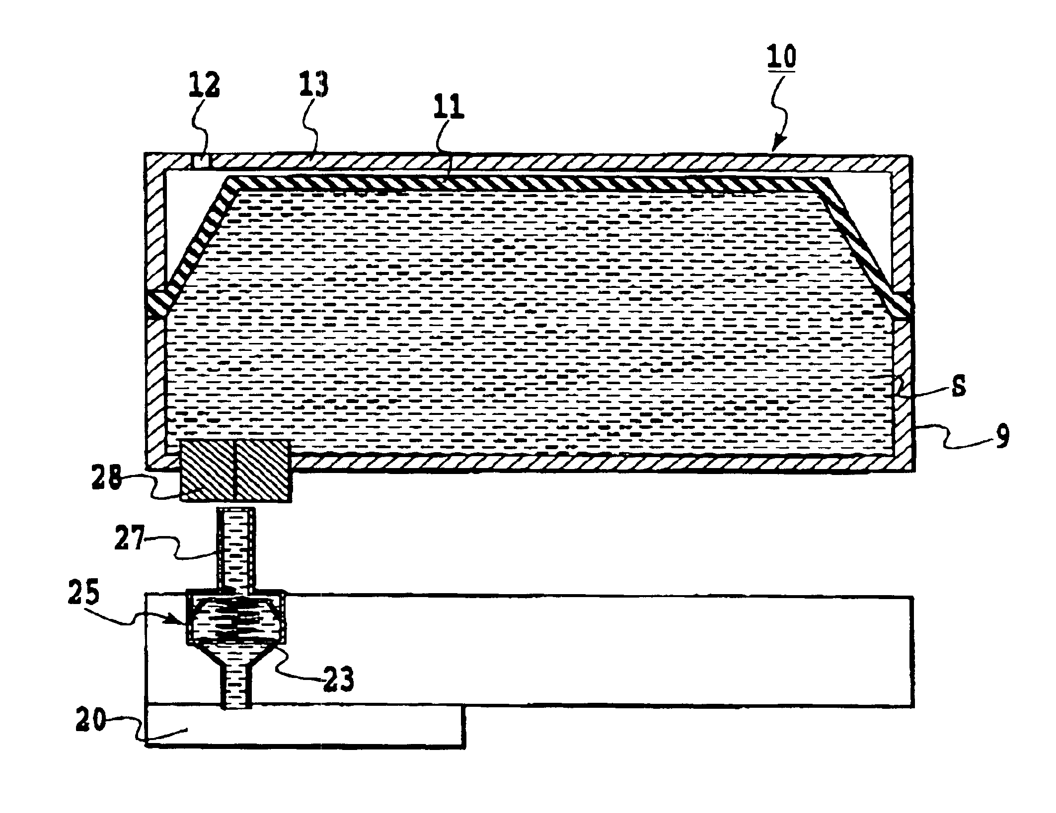
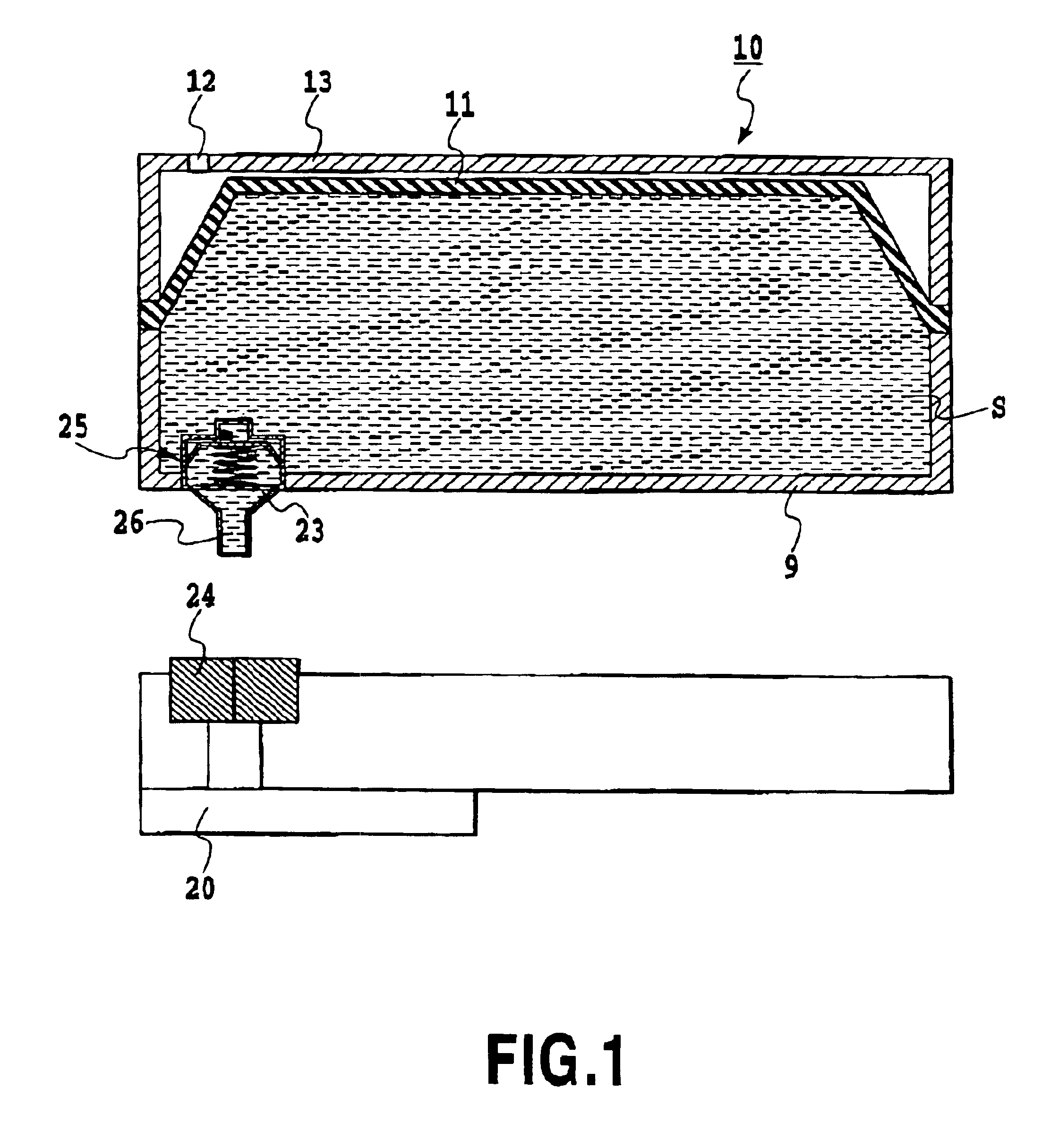
FIG. 1 shows a first embodiment of the liquid supply system according to the invention having a liquid container integrated with a one-way valve for controlling a liquid supply.

Referring now to FIG. 1, denoted 10 is an ink tank (also called an ink cartridge) that is a cartridge-type liquid container capable of retaining ink, and 20 is an inkjet print head working as the liquid using unit that can eject ink supplied from the ink tank 10. Although the ways of ink ejection from the inkjet print head 20 are not specified here, thermal energy generated by a thermoelectric converter may be used as the energy for ejecting ink, for example. In such a case, the heat generated by the thermoelectric converter produces film boiling from the ink and the energy of generated bubbles allows ink to be ejected out of the ink ejection port. If the ink tank 10 and the inkjet print head 20 in this embodiment are separably coupled with each other, a detachable inkjet cartridge can be pr...

second embodiment

(Second Embodiment)

FIGS. 5-8 are the drawings that illustrate a second embodiment of the present invention.

As shown in FIG. 5, the basic structure of the liquid supply system according to the second embodiment is the same as that of the first embodiment. In FIG. 5, denoted 110 is a cartridge-type ink tank (or ink cartridge) that can hold ink, and 120 is a print head that can eject ink supplied from the ink tank 110. The mode of ink ejection in the print head 120 is not specified, as is the case with the first embodiment. For example, thermal energy generated by a thermoelectric converter may be used as the energy for ejecting ink. In such a case, the heat generated by the thermoelectric converter produces film boiling from the ink and the energy of evolving bubbles allows ink to be ejected out of the ink ejection port. If the ink tank 110 and the print head 120 are separably coupled with each other, a detachable inkjet cartridge can be prepared for the inkjet print apparatus. Then i...

third embodiment

(Third Embodiment)

FIG. 9 is a diagram illustrating a third embodiment of the present invention.

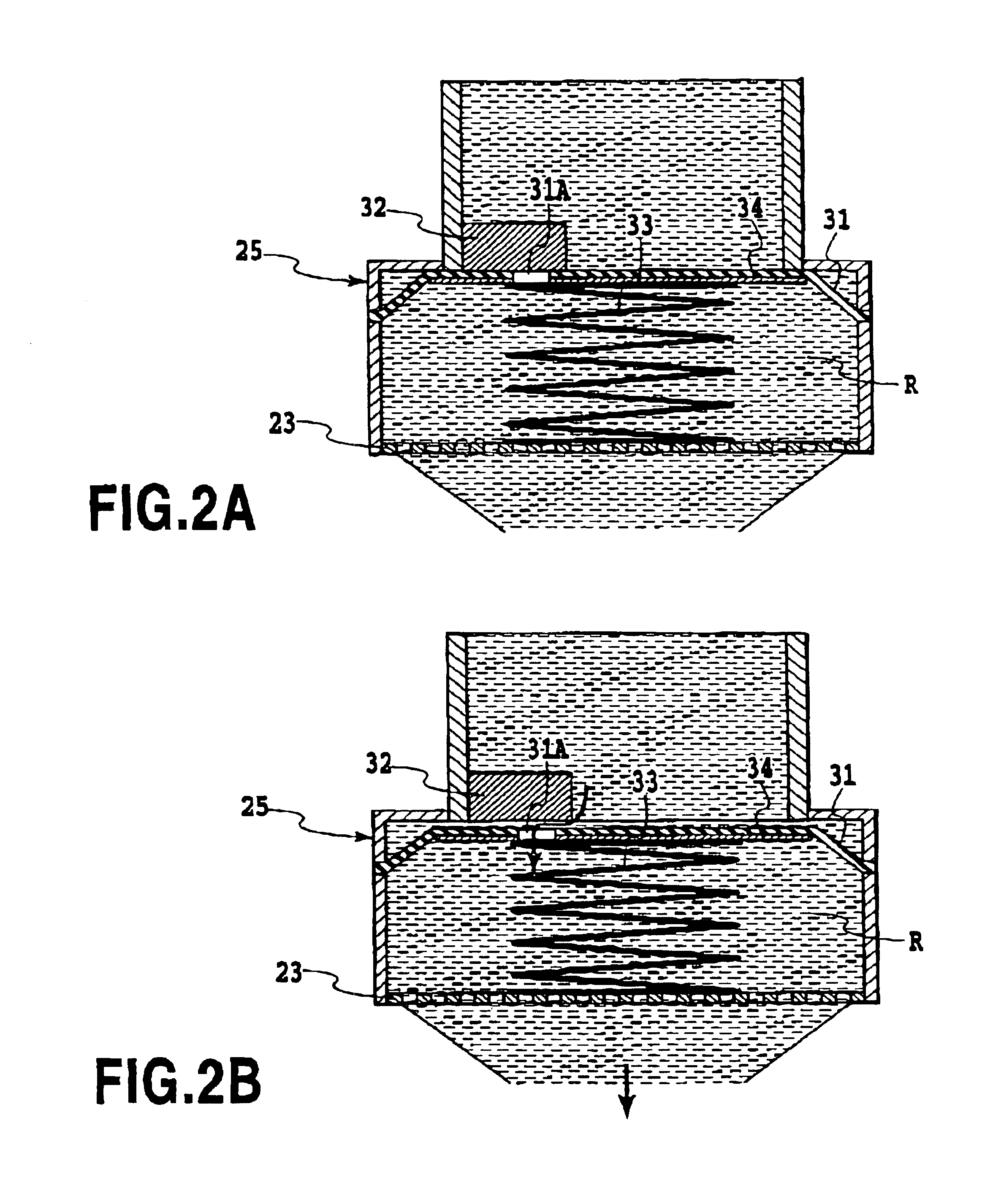
In this embodiment, a one-way valve unit 130a for controlling a liquid supply, which is similar to the one-way valve unit 25 shown in FIGS. 1, 2A, 2B, and a one-way valve unit 130b for controlling a liquid supply, which is similar to the one-way valve unit 130 for introducing gas or liquid shown in FIGS. 5-8, are provided in the liquid container.

This embodiment has a one-way valve unit 130a for controlling a liquid supply equipped with a hollow needle 126 in the liquid supply unit of the ink tank 110. The gas (or liquid) introduction unit of the ink tank 110 is closed by a rubber plug 118 which isolates the containing space S from the outside. On the other hand, the print head 120 has a rubber plug (rubber lid) 124 in the position corresponding to the liquid supply unit of the ink tank 110 to isolate the ink supply passage in the print head 120 from the outside. The print head also has a o...


PUM


Abstract

The present invention prevents liquid leakage regardless of the using conditions and the reserving atmosphere and stabilizes a negative pressure regardless of the degree of liquid consumption, by having a one-way valve in the liquid container that supplies liquid to an external device, maintaining the negative pressure formed in the liquid supplying passage positioned in the downstream of a position where liquid or gas is supplied by the one-way valve. The liquid container has a deformable, movable unit at least a part of which is made of a flexible material. A space other than the liquid supply unit forms a substantially sealed space in which liquid is retained. The container is capable of supplying the liquid to the outside. Such container has a one-way valve that passes liquid or gas from the liquid container to the outside or from the outside to the liquid container.

Description

This application is based on Japanese Patent Application Nos. 2001-310649 filed Oct. 5, 2001 and 2001-398219 filed Dec. 27, 2001, the contents of which are incorporated hereinto by reference.BACKGROUND OF THE INVENTION1. Field of the InventionThe invention relates to a liquid container that supplies liquids such as ink to a liquid using unit of a recording unit such as a pen and a print head; a liquid supply system that is the combination of such a liquid container and liquid using unit; and a liquid using apparatus employing such a liquid supply system, an ink tank, an ink supply system, inkjet print head and a print apparatus employing such an ink supply system.2. Description of the Related ArtSome of the liquid using apparatuses, such as an inkjet print apparatus that forms images on a printing medium by applying a liquid ink thereon using an inkjet print head, form images on a printing medium by moving a print head thereover and ejecting ink thereto. Others may form images by mo...

Claims


Application Information

Patent Timeline
Patent Type & Authority Patents(United States)
IPC IPC(8): B41J2/175
CPCB41J2/17523
Inventor ISHINAGA, HIROYUKIKUWABARA, NOBUYUKIOHASHI, TETSUYAINOUE, RYOJIOGURA, HIDEKI
Owner CANON KK
Why Eureka
Try Eureka