Umbrella planter with a snap-on base

a planter and umbrella technology, applied in the field of umbrella planters with snap-on bases, can solve the problem that none of the aforementioned umbrella planters includes internal features for self-wicking water

Inactive Publication Date: 2005-03-08
MISCO ENTERPRISES
View PDF15 Cites 24 Cited by
  • Summary
  • Abstract
  • Description
  • Claims
  • Application Information

AI Technical Summary

Problems solved by technology

Additionally, none of the aforementioned umbrella planter includes internal features for the self-wicking of water to the plants, an overflow control of the water, stacking ribs for shipping of multiple units and a stacking spacer for multiple unit displaying.

Method used


Image

  • Umbrella planter with a snap-on base
  • Umbrella planter with a snap-on base
  • Umbrella planter with a snap-on base

Examples


embodiment 10

PREFERRED EMBODIMENT 10

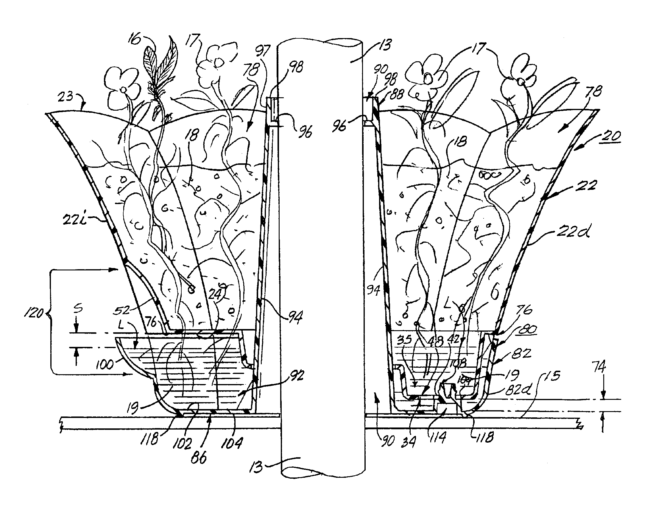
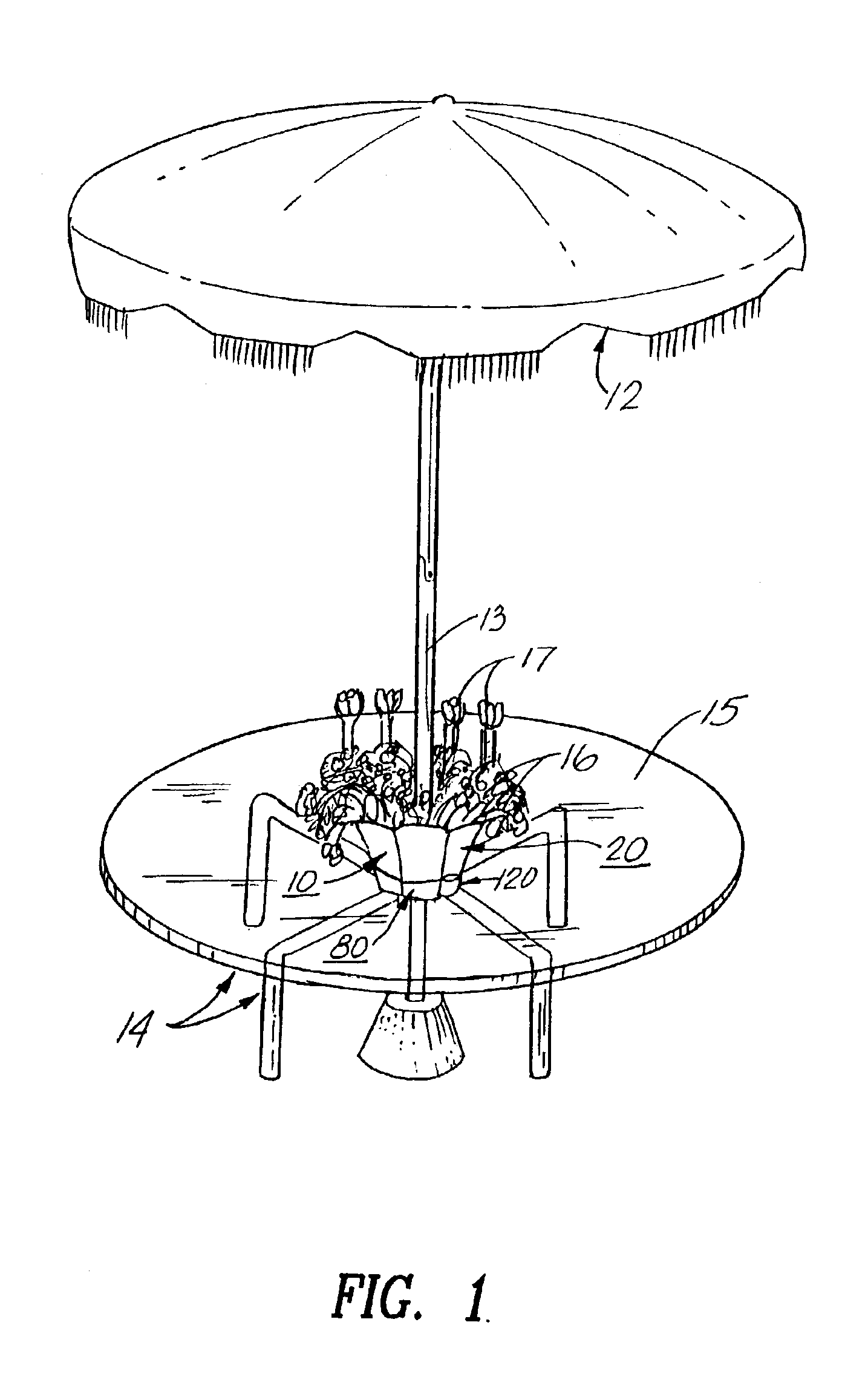
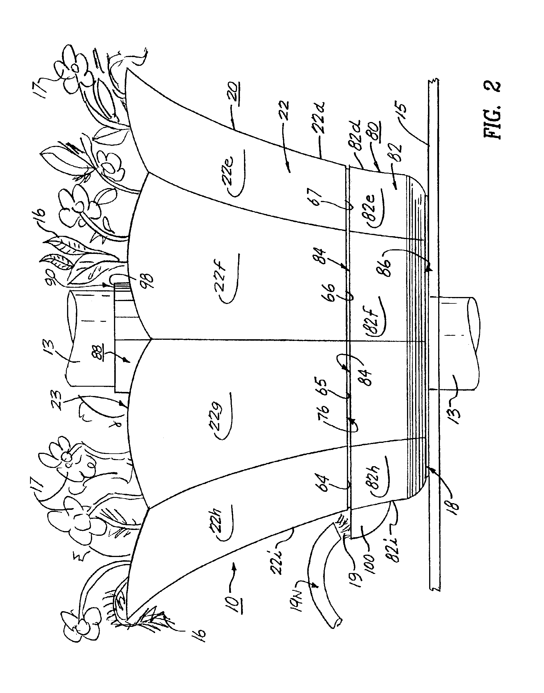
The umbrella planters 10 and its component parts of the preferred embodiment of the present invention are represented in detail by FIGS. 1 through 13 of the patent drawings. The umbrella planter 10 includes a snap-on lower water reservoir base member 80, as shown in FIGS. 1 to 3 of the drawings, is used for providing the planter receptacle 10 having a centralized tapered hollow center tubular sleeve 88 with a central sleeve opening 90 for receiving an umbrella pole 13 of a patio umbrella 12. The planter receptacle 10 is also used for a centralized placement on the table top 15 of the patio table 14, wherein the planter receptacle 10 can hold and contain plants 16, flowers 17, potting soil 18 and water 19.

The umbrella planter 10, as shown in FIGS. 1 through 10 of the drawings, includes an upper planter member 20 having a conventionally shaped truncated outer conical side wall 22 (being divided into 9 equal sections 22a to 22i) with an upper circular perimeter e...

second embodiment 200

SECOND EMBODIMENT 200

The umbrella planter 200 and its component parts of the second embodiment of the present invention are represented in detail by FIGS. 13 to 16 and 16A of the patent drawings. All aspects of the second embodiment of the umbrella planter 200 are the same as the preferred embodiment of the umbrella planter 10 except for the shape and configuration of the side wall 222 of the upper planter member 220 and also the shape and configuration of the side wall 282 of the lower base member 280 with the overall configuration of the umbrella planter 200 being a truncated conical shape. Another exception is the shape and configuration of the plurality of connector openings 240, 242 and 244 being square-shaped and the shape and configuration of the connecting support pads 290, 292 and 294 being square-shaped, as shown in FIG. 16 of the drawings. The umbrella planter 200 of the second embodiment, as shown in FIGS. 14 and 15 of the drawings, is used for providing the planter rece...

third embodiment 300

THIRD EMBODIMENT 300

The umbrella planter 300 and its component parts of the present invention are represented in detail by FIGS. 17 and 17A of the patent drawings. All aspects of the third embodiment of the umbrella planter 300 are the same as the preferred embodiment of the umbrella planter 10 except for the shape and configuration of the side wall 322 of the upper planter member 320 and also the shape and configuration of the side wall 382 of the lower base member 380 with overall configuration of the umbrella planter 300 being a truncated conical shape having side walls 322 and 382 with a concave shape. Other exceptions are the shape, configuration and array of the plurality of connector openings 340, 342, 344, 346 and 348 being rectangular-shaped within each of the hollow legs 330, 332, 334, 336 and 338 being arrayed in a pattern of radiating legs, and the shape and configuration of the connecting support bars 390, 392, 394, 396 and 398 being rectangularly-shaped and arrayed in ...


PUM


Abstract

An umbrella planter having a snap-on lower water reservoir base member and a center sleeve tube for use with an umbrella-type patio table having a table top with a centrally located opening for receiving an umbrella pole of an umbrella assembly. The umbrella planter includes an upper planter member and a lower water reservoir base member. The lower water reservoir base member includes a side wall having an upper perimeter lip and a bottom base wall; and includes a hollow center sleeve connected to the bottom base wall and having a central sleeve opening for receiving the umbrella pole therethrough; and the bottom base wall also includes an upper surface and a lower surface. The upper surface of the bottom base wall of the lower base member includes first connecting means for connecting and mating the lower base member to the upper planter member. The upper planter member includes a side wall having an upper perim eter edge, and a bottom planter wall having a plurality of water ventilation slots; the bottom planter wall has a centralized pedestal section connected thereto; and also the bottom planter wall has an upper surface and a lower surface. The pedestal section includes an inner cylindrical wall forming a sleeve receiving passageway for receiving the hollow center sleeve therein; the inner cylindrical wall having a plurality of downwardly protruding hollow legs being integrally attached thereto.

Description

FIELD OF THE INVENTIONThe present invention relates to an umbrella planter having a snap-on base that is adapted for encircling an umbrella pole for use with an umbrella-type patio table. More particularly, the umbrella planter has a centrally located hollow center tubular sleeve with a central sleeve opening for receiving the umbrella pole there through, such that the umbrella planter is centrally positioned on the patio table top and the umbrella pole is extended through the central sleeve opening of the planter housing.BACKGROUND OF THE INVENTIONPresently, umbrella-type patio tables have become very popular for use in home backyards, pool areas, private gardens and on private patios, as well as at restaurants, cafes, swim clubs, golf and tennis clubs, hotels, and the like. Essentially, such umbrella-type patio tables are comprised of a table top and legs to support the table top in a generally horizontal orientation and an umbrella assembly mounted on a supporting member which ex...

Claims


Application Information

Patent Timeline
Patent Type & Authority Patents(United States)
IPC IPC(8): A01G9/02A01G13/02
CPCA01G13/0212A01G9/02
Inventor MISSRY, EZRA
Owner MISCO ENTERPRISES
Why Eureka
Try Eureka