Printhead with plural arrays of printing elements

Inactive Publication Date: 2005-03-08
XEROX CORP
View PDF13 Cites 7 Cited by
  • Summary
  • Abstract
  • Description
  • Claims
  • Application Information

AI Technical Summary

Benefits of technology

In the driver circuitry of the printhead, a first portion of the driver circuitry comprises an arrangement of plural rows of printing-element drivers and plural rows of wire-bonding pads. The plural rows of printing-element drivers are interconnected to respective ones of the printing elements of the first array of printing elements via respective pads of the plural rows of wire-bonding pads, wherein the arrangement of plural rows of printing-element drivers and plural rows of wire-bonding pads reduces a spacing of the printing elements for improved resolution of the latent image.
In accordance with various embodiments of the invention, the pitch of the printing elements in the first array of printing elements may be equal to the pitch of the printing elements in the second array of printing elements, and the imaging electronics may activate the printing elements of the first and the second arrays in checkerboard fashion, or in random fashion. The checkerboard or random modes of operation serve to break up any unwanted pattern in the latent and printable images resulting from a defective print element and, thereby, counteract an observer's perception of a streak or line imperfection in the image. Alternatively, the imaging electronics may activate the printing elements of the first and the second arrays in a mode of reduced intensity of light emitted from the printing elements while directing the printing elements of the second array to print the same data as is printed by the printing elements of the first array to compensate for the reduced intensity of the emitted light, thereby to extend the lifetime of the printing elements. In addition, the imaging electronics may activate the printing elements of the first a

Problems solved by technology

Due to the construction of printheads with a single line of LEDs, a faulty diode introduces a noticeable pattern in the printed image out

Method used


Image

  • Printhead with plural arrays of printing elements
  • Printhead with plural arrays of printing elements
  • Printhead with plural arrays of printing elements

Examples


Embodiment Construction

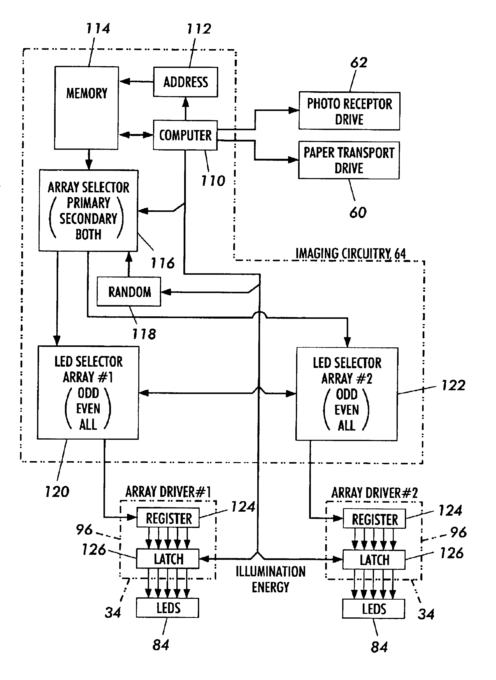
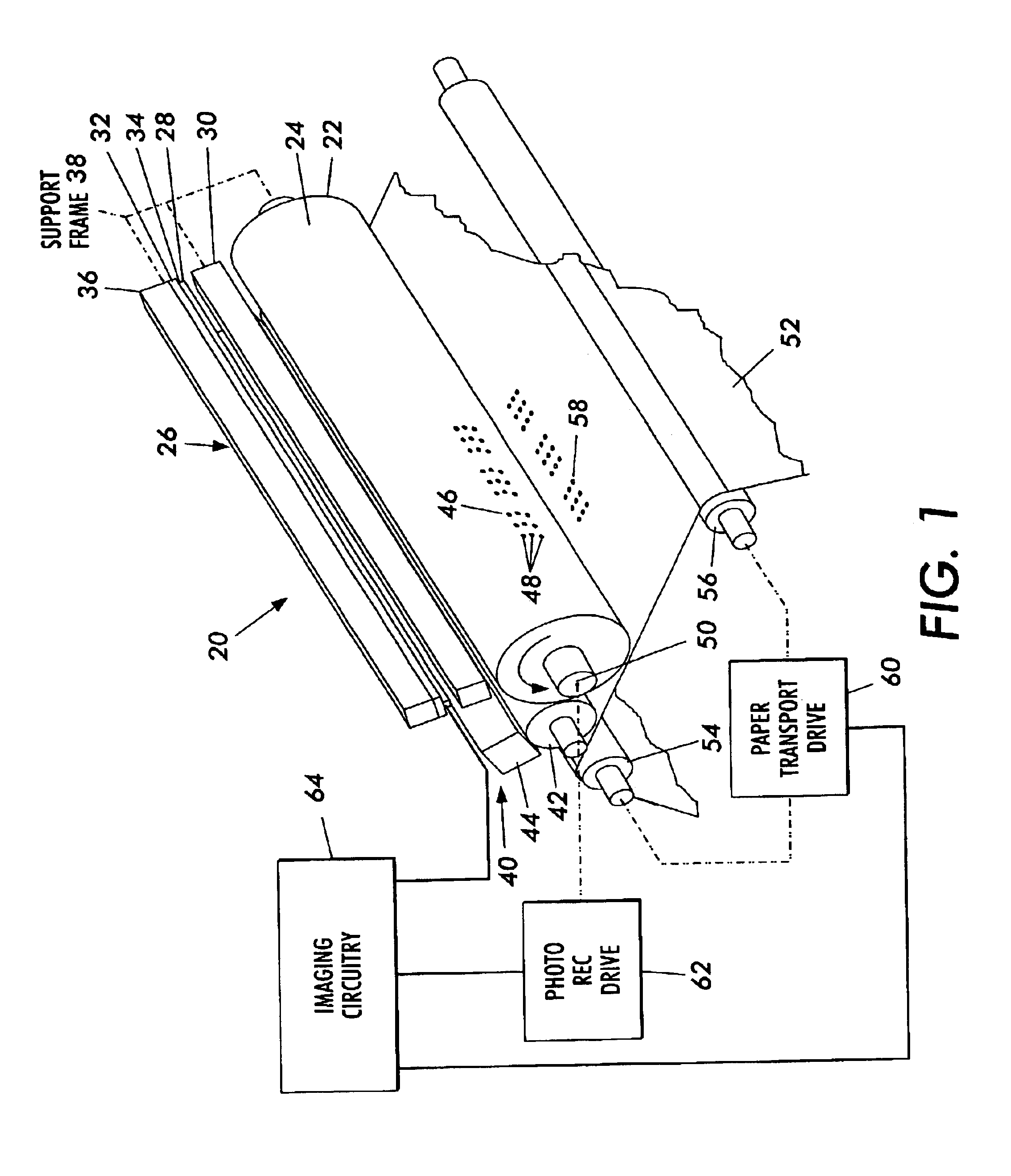
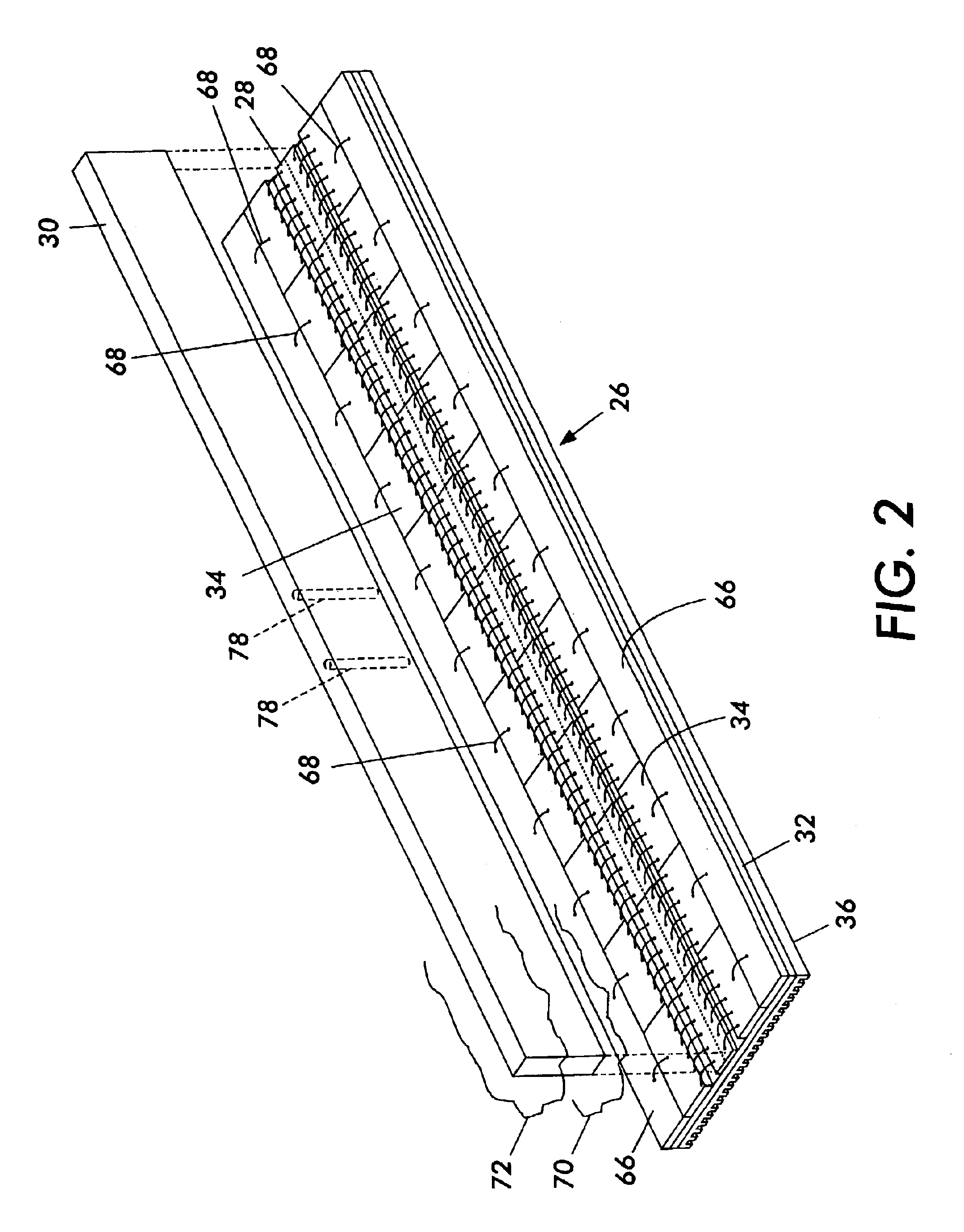
With reference to FIG. 1, a xerographic printing engine 20 comprises a photoreceptor 22 in the form of the cylindrical drum with an outer image receiving surface 24 of photosensitive material, and a printhead 26. The printhead 26 has an elongated shape, in the form of a bar, and includes printing elements in the form of sources of light. In a preferred embodiment of the invention, the sources of light are provided by an assembly 28 of LEDs which radiates light through an optical focusing element in the form of an elongated group of fibers of a lens 30 to produce a latent image on the receiving surface 24. The LED assembly 28 is mounted on a substrate 32 which also carries LED driver circuitry 34, wherein heat produced by the driver circuitry 34 and the LED assembly 28 is dissipated by a heat sink 36 disposed on a backside of the substrate 32 opposite the LED assembly 28. Also included in the printhead 26 is a frame 38 which holds the lens 30 adjacent to, but with a small spacing fro...


PUM


Abstract

A xerographic print engine employs a photoreceptor with an image receiving surface, a printhead for directing light to the photoreceptor to produce thereon a latent image, and a developer for converting the latent image to a printable image to be transferred from the photoreceptor to a print medium during a relative motion between the photoreceptor and the print medium. The printhead has light emitting diodes disposed in plural rows arranged alongside each other on a substrate which also supports driver circuitry connecting with imaging electronics for activating individual ones of the diodes. An optical element focuses light of the diodes onto a row of the latent image, the focussing being accomplished concurrently for individual ones of the diodes located in a plurality of the rows.

Description

BACKGROUND OF THE INVENTIONThis invention relates to a printhead for a printing engine, such as a xerographic printing engine, having printing elements arranged in a plurality of arrays and, more particularly, to a printhead with separately energizable parallel arrays of light emitting elements positioned for illumination of a common region of image space.Xerographic print engines are constructed, typically, with a drum of photosensitive material providing a photoreceptor surface for receipt of a latent image, the drum being operated in conjunction with a developer that converts the latent image to a printable image by use of electrostatic charges for securing toner particles to the photoreceptor surface at the latent image. The latent image is produced by a printhead having sources of light, such as a single line of light-emitting diodes (LEDs) serving as points of an object to be imaged, and an elongated optical focussing element which focuses the line of LEDs upon the photorecept...

Claims


Application Information

Patent Timeline
IPC IPC(8): B41J2/45B41J2/44B41J2/455H04N1/036
CPCB41J2/451
Inventor CORONA, STEPHEN C.DRAKE, DONALD J.
Owner XEROX CORP
Why Eureka
Try Eureka