
Roof structure for folding tent frame

a tent frame and roof structure technology, applied in tents/canopies, building types, constructions, etc., can solve the problems of increasing the cost of manufacturing such a tent frame, adding to the overall weight of the tent frame, and requiring extra installation space (i.e., height)

Inactive Publication Date: 2005-03-22
CARAVAN CANOPY INTL INC
View PDF28 Cites 70 Cited by
  • Summary
  • Abstract
  • Description
  • Claims
  • Application Information

AI Technical Summary

Benefits of technology

In accordance with a sixteenth embodiment of the invention, the eleventh embodiment is further modified so that each protruding hinge has a cut out portion forming an operation space contiguous with a hole penetrating through the operation space, and a spherical pivotal member is disposed on the one end of each upper pole, wherein each spherical pivotal member is inserted into one operation space so as to couple the spherical pivotal member to the protruding hinge.

Problems solved by technology

One drawback of such conventional foldable tent roof structures is that the configuration requires a center post, or central support member, and several central scissor assemblies connected together to lift the center post, or central support member, upwards into its vertically extended or deployed position.
These added structures add to the overall weight of the tent frame, and the cost to manufacture such a tent frame is inevitably increased.
Moreover, because the roof invariably forms an angular pyramid or triangular shape (i.e., a “” shape), extra installation space (i.e., height) is required.
Lastly, the protruding top or center post is likely to be affected by strong winds.
However, the trade off is that these roof structures are relatively flexible and flimsy, which means that these structures tend to collapse in strong winds or have profiles that are lowered.
However, there is a demand for lightweight tent structures that have reinforced, lightweight roof structures that avoids this flexible, collapsible feature because many consumers do not want a tent with a roof that will collapse or lower its profile in strong winds.
The drawback of the canopy disclosed by Carter '572 Patent is that flexible, collapsible pole members must be inserted into the clip members when collapsed, which adds to the complexity of storing and deploying the canopy.
As mentioned above for the Carter '193 Patent, the drawback of the canopy of the Carter '293 patent is that the canopy may flex into the lowered position during strong winds, thereby striking or otherwise interfering with people taking shelter underneath the canopy.
As mentioned above for the Carter '193 Patent, the drawback of the canopy of the Carter '312 patent is that the canopy may flex into the lowered position during strong winds, thereby striking or otherwise interfering with people taking shelter underneath the canopy.
As mentioned above for the Carter '193 Patent, the drawback of the canopy of the Carter '940 patent is that the canopy may flex into the lowered position during strong winds, thereby striking or otherwise interfering with people taking shelter underneath the canopy.
First, the shape of the roof structure approximates an angular pyramid or triangular shape, which has a limiting effect on the amount of headroom provided under the canopy placed on the roof structure.
This structure of the Carter '902 Patent has the drawback of unnecessarily complicating the manufacture of the canopy without a substantial benefit.
However, the tent structure disclosed by the Tsai Patent includes a cumbersome and specialized hinge (“intermediate pivot connecting member”) between the first and second rod members that form the roof structure.

Method used


Image

  • Roof structure for folding tent frame
  • Roof structure for folding tent frame
  • Roof structure for folding tent frame

Examples


Embodiment Construction

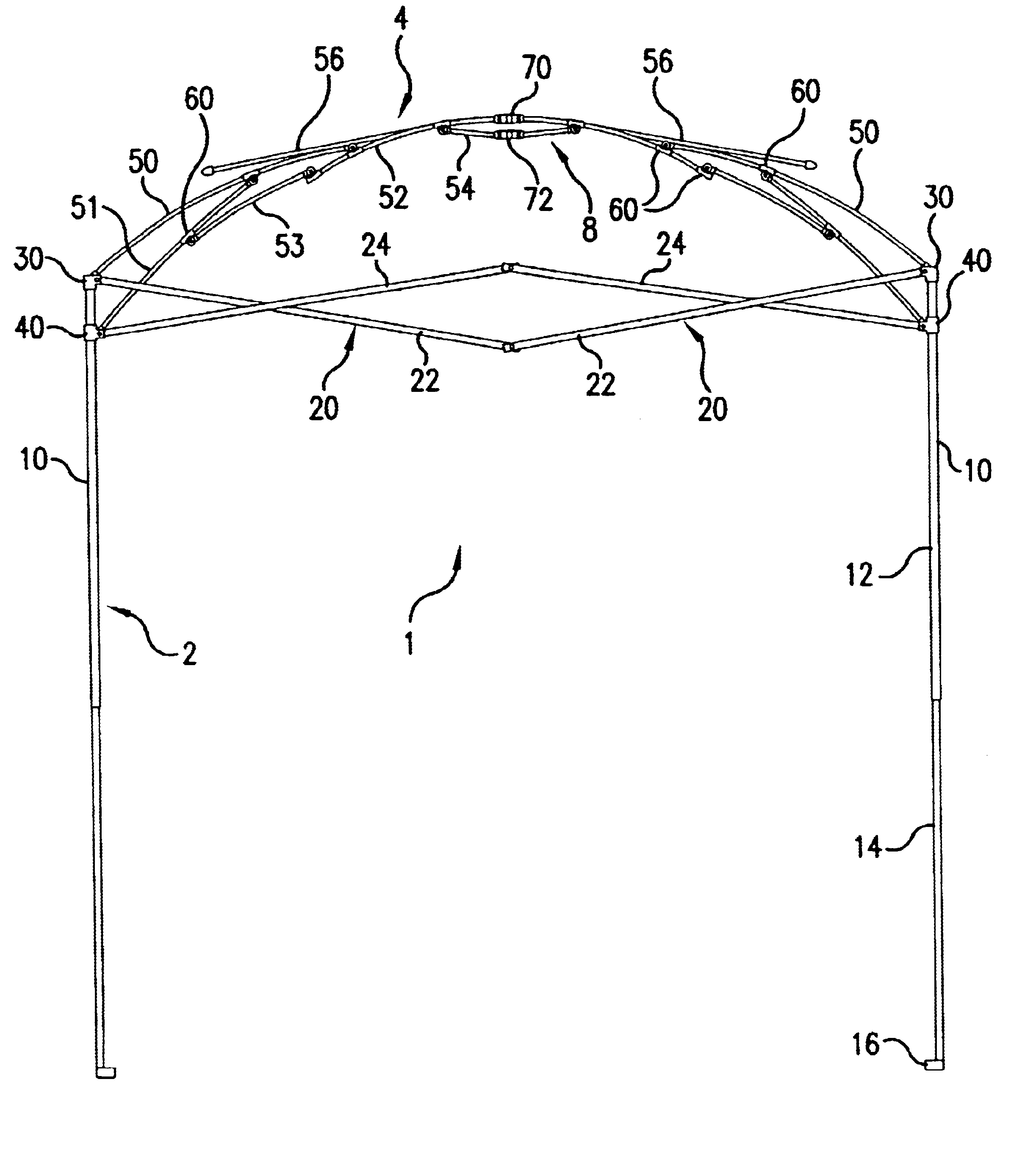
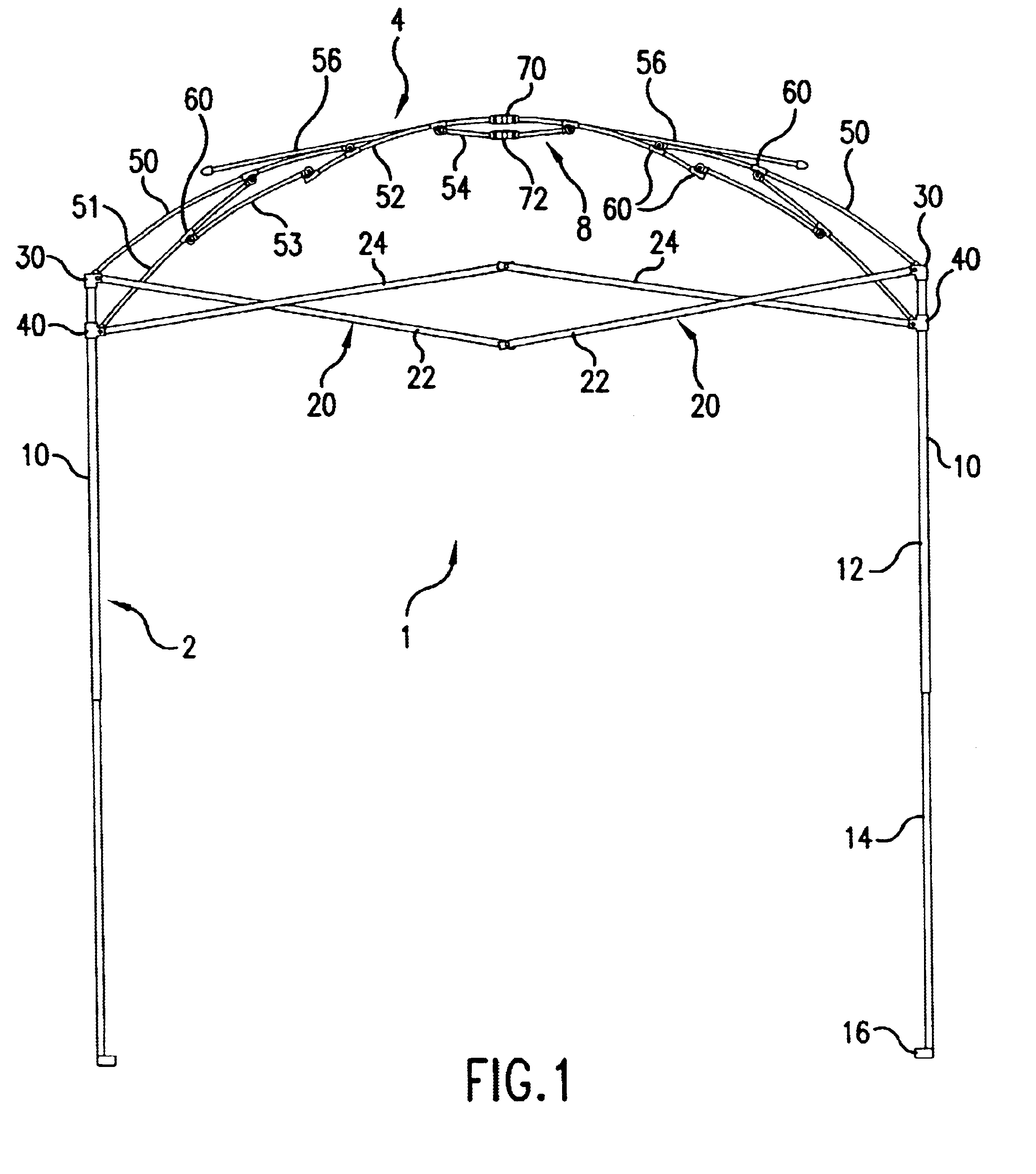
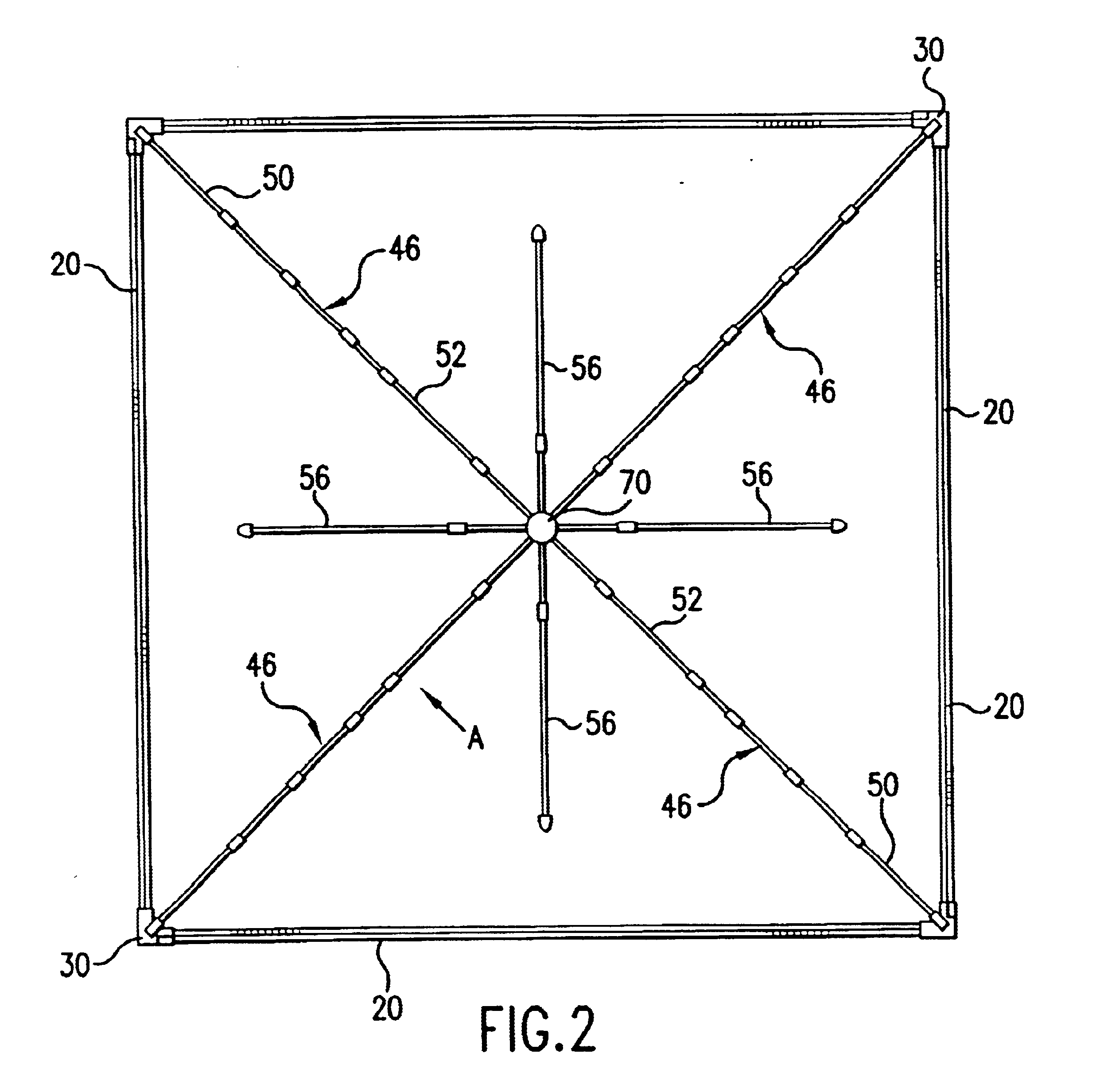
The apparatus of the present invention is a portable, foldable tent structure having a roof assembly supported by a roof support assembly that applies force to the bowable poles of the roof assembly so as to configure the roof assembly into a dome shape when the foldable tent structure is deployed in the extended state.

FIG. 1 and FIG. 2 schematically depict frontal and plan views, respectively, of the tent frame structure 1 in accordance with the present invention showing the overall configuration of the structure in an unfolded state. The unfolded state may also be referred to as the “expanded state” or the “deployed” state. FIG. 12 schematically depicts the tent frame structure 1 in the folded state. The folded state may also be referred to as the “collapsed state” or the “non-deployed state.” The foldable tent frame structure 1 is generally rectangular shape, although the frame could be constructed to have a triangular shape, a pentagonal shape or other generally polygonal shape ...


PUM


Abstract

A tent frame including: leg posts; a plurality of expandable connectors connected in pairs between adjacent posts, each connector having first and second outer ends and is fixedly connected at the first outer end to the upper end of one post and slidably connected at the second outer end to a lower portion of the same post, each connector movable between extended and folded states; a roof comprising upper poles, each pivotally connected to a post and to a central pole, each upper pole and corresponding central pole are movable between an extended and folded states; and support pole assemblies, each connected at one end to slide with a second outer end and at another end to a central pole so that each connector, upper pole and central pole expand together to the extended state and the support pole assemblies support the central poles to maintain the extended state.

Description

FIELD OF THE INVENTIONThe present invention pertains generally to a roof structure for a foldable tent frame, such as might be used, for example, at conventions, parties, weddings, fairs, carnivals, outdoor sporting events and the like. More particularly, the present invention provides a roof structure for a foldable tent frame that has a simple structure, is lightweight, and provides a pleasing new geometrical form. Specifically, the roof structure for a foldable tent frame in accordance with the present invention has a gently curved roof with an upwardly protruding center that moves into the expanded or deployed position as the four leg poles of the tent frame assembly unfold into the expanded or deployed position. The roof structure in accordance with the present invention achieves its unique curved geometry without the need of an upright central post to support the center of the tent as is commonly seen in the roof structures of conventional foldable tents.BACKGROUND OF THE INVE...

Claims


Application Information

Patent Timeline
Patent Type & Authority Patents(United States)
IPC IPC(8): E04H15/34E04H15/48E04H15/50E04H15/44
CPCE04H15/50E04H15/48E04H15/44
Inventor SUH, DONG WOOG
Owner CARAVAN CANOPY INTL INC
Features
  • Generate Ideas
  • Intellectual Property
  • Life Sciences
  • Materials
  • Tech Scout
  • Unparalleled Data Quality
  • Higher Quality Content
  • 60% Fewer Hallucinations
Learn More