Track and track assembly for a track laying vehicle

a technology for track laying vehicles and track rollers, which is applied in endless track vehicles, mechanical devices, transportation and packaging, etc., can solve the problems of track rollers climbing, belts being misaligned, and limited lug height, and achieve good guiding surface and substantial height

Inactive Publication Date: 2005-03-22
DEERE & CO
View PDF39 Cites 31 Cited by
  • Summary
  • Abstract
  • Description
  • Claims
  • Application Information

AI Technical Summary

Benefits of technology

Because the guide portion of the lug does not engage with the teeth of the sprocket, the drive portion moves freely into and out of engagement with a tooth on the sprocket. Thus it can have a fairly substantial height and provide a good guiding surface that will maintain track alignment when the track is operating on an incline and / or the vehicle is being turned.

Problems solved by technology

The height of the lugs are generally limited because of potential interference between the lugs and the teeth of the drive sprocket as the lugs enter and leave the sprocket.
Because there is no locking mechanism and the height of the lugs are limited, the belt can become misaligned.
For instance, when the vehicle is turned the belt is forced to slide on the ground and the resistance to this sliding causes substantial belt misalignment forces to be produced which may force the track rollers to climb over the lugs.
Also, when the vehicle is on a hillside, the weight of the vehicle tends to shift the vehicle downhill.
But this movement is resisted by engagement of the track with the ground, again generating misalignment forces which may cause the rollers to climb over the adjacent lugs.
As the rollers climb over the lugs, the track is detracked and the driving engagement between the lugs and drive sprocket is lost.

Method used


Image

  • Track and track assembly for a track laying vehicle
  • Track and track assembly for a track laying vehicle
  • Track and track assembly for a track laying vehicle

Examples


Embodiment Construction

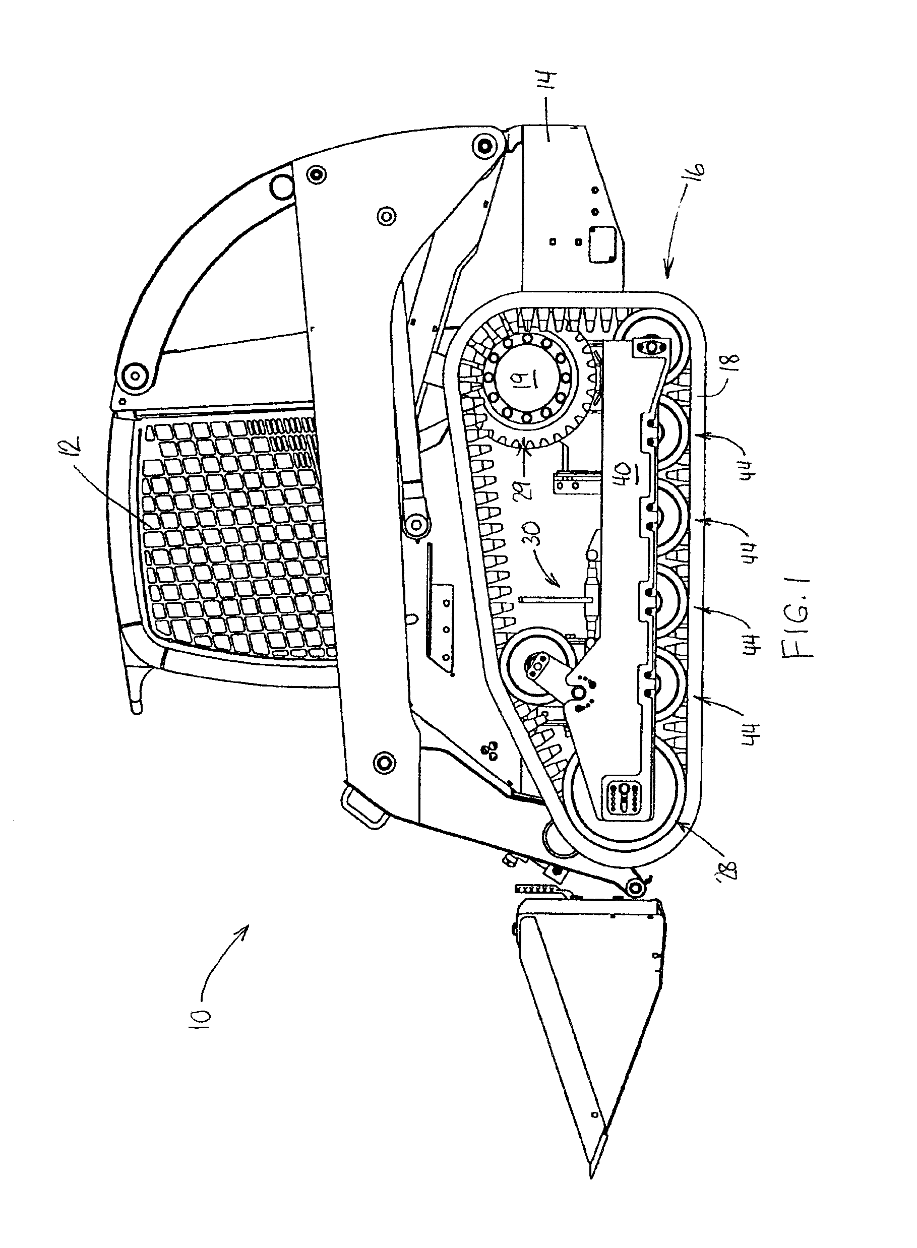
Looking first to FIG. 1, there is shown a vehicle in the form of a skid-steer loader 10. At its mid-section, the vehicle includes an operator's station 12 supported upon the vehicle frame 14. The frame is supported by a track assembly or undercarriage 16 on each side. Each track assembly includes a ground engaging track 18 powered by a hydraulic motor 19.

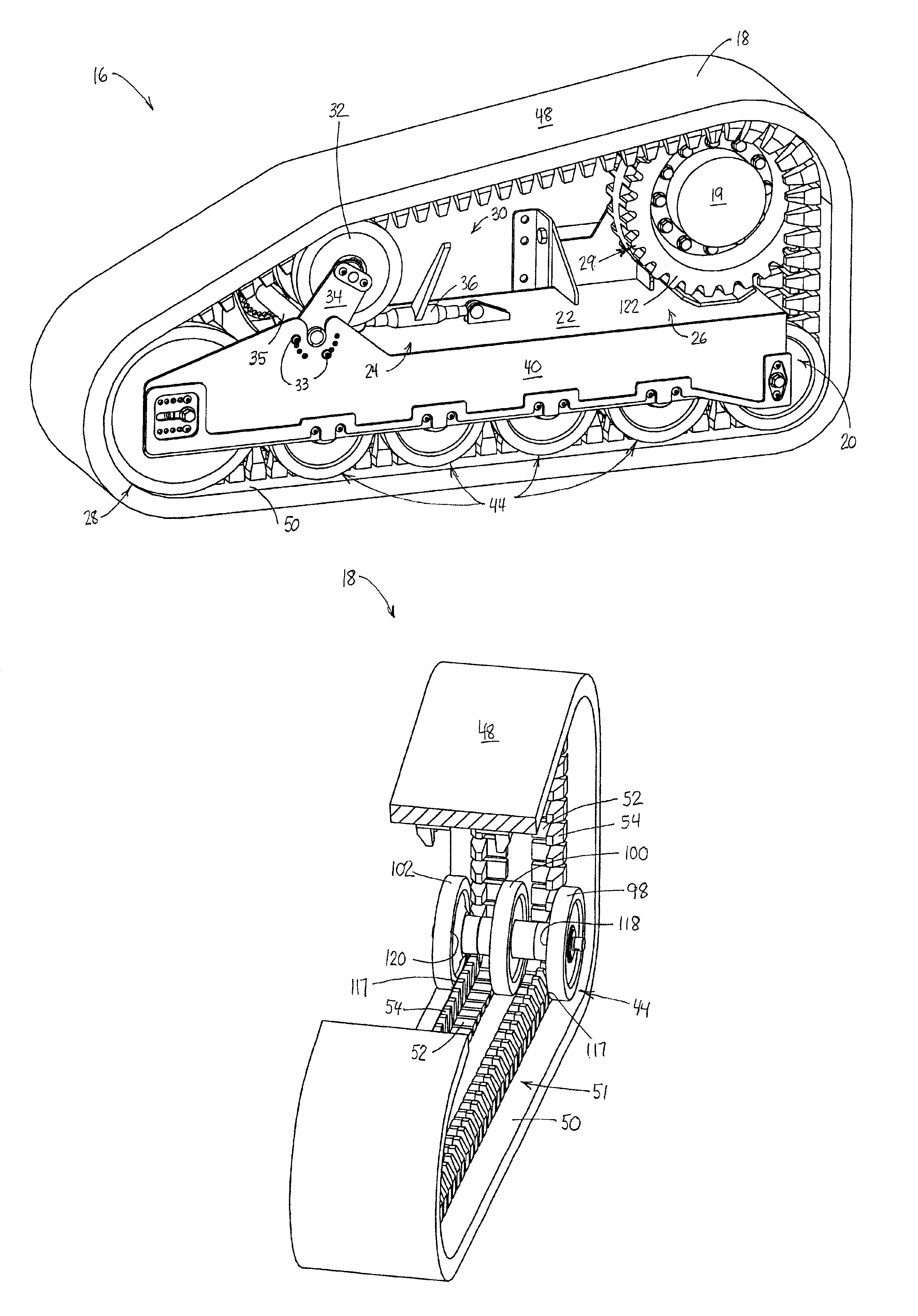
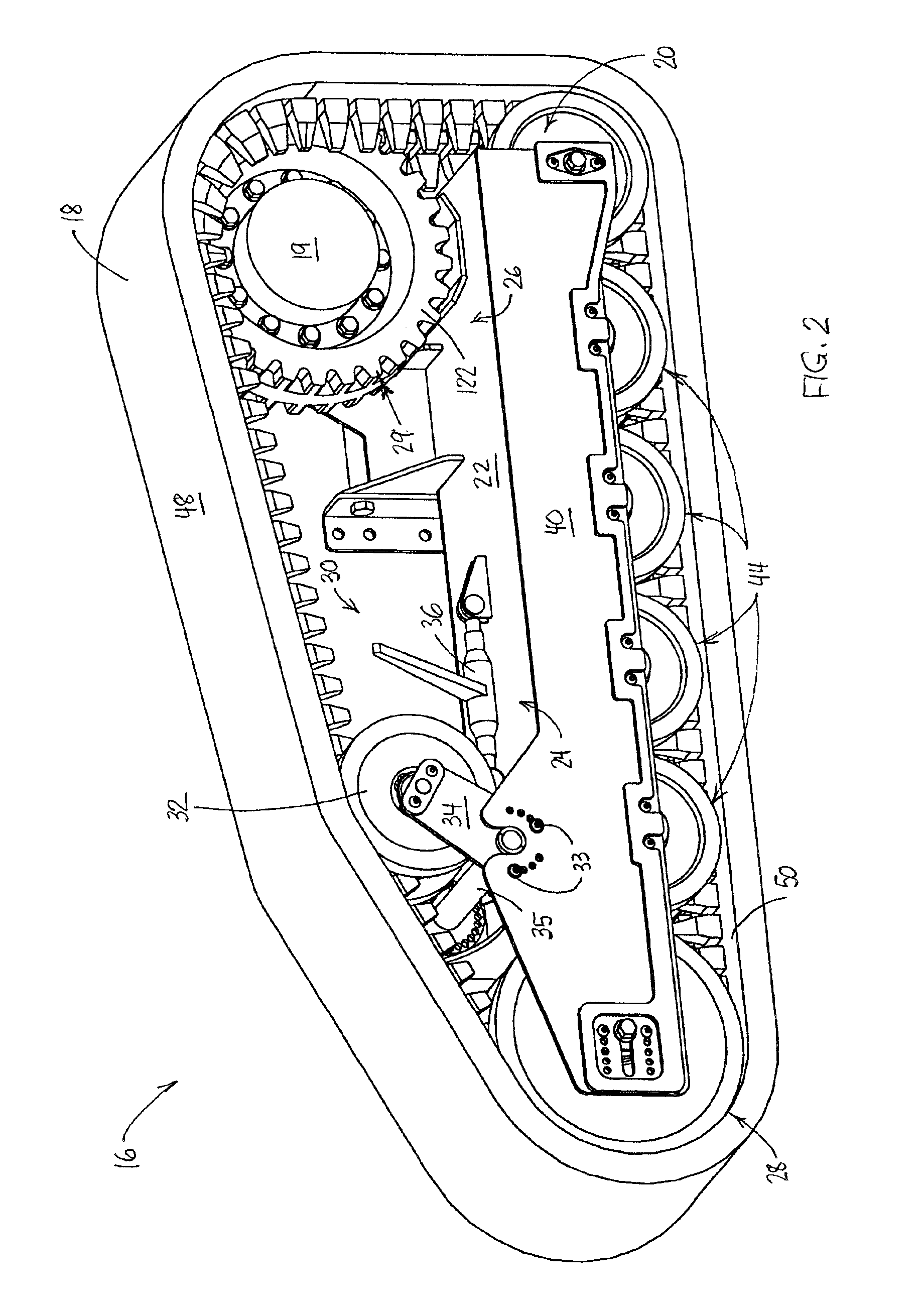
Looking next to FIG. 2, a track assembly 16 is shown in more detail. The assembly 16 includes a frame subassembly 20 having a top, center plate 22 and side plates 40. An idler wheel 28 is held at a first or front end 24 of the subassembly. A drive sprocket 29 is provided at the rear or second end 26 of the subassembly for transferring power from the motor 19 to the track 18. A tensioning device 30 is supported on the top plate 22 between the idler 28 and sprocket 29.

Preferably, and as shown in FIGS. 4-6, the tensioning device 30 includes a plurality of wheels 32 mounted on an axle supported at the free ends of arms 34. The arms 34 a...


PUM


Abstract

A track assembly for moving a vehicle which includes a track having lugs including both drive and guide portions on its inner surface. The guide portions substantially abut against the track rollers of the assembly. Such abutment maintains alignment of the track between those rollers so as to prevent it from moving from side to side and interfering with feeding of the drive portions onto the assembly drive sprocket. Further, the guide portions grab against the drive sprocket to maintain contact of the drive portions therewith. Each of the above functions permits uninterrupted movement of the vehicle since the track is enabled to move in a continued path.

Description

FIELD OF THE INVENTIONThis invention relates generally to a track and track assembly for a track laying vehicle, and more specifically, to a track assembly including a track having lugs which resist movement of the track from the vehicle drive sprocket and from the track rollers associated with the track.BACKGROUND OF THE INVENTIONThe tracks of track laying vehicles are often made of an elastomeric material and have similarly constructed raised projections or lugs on an inner surface. In positive drive tracked vehicles, these lugs fit into grooves created between the teeth of a drive wheel or drive sprocket which, together with a series of track rollers and an idler, define a path along which the track moves. As the track moves along this path, the lugs serve at least two purposes. First, they provide surfaces on the track which a drive sprocket can grab to move the track and thus, the vehicle. Second, the lugs maintain alignment of the track with the sprocket, idler and track rolle...

Claims


Application Information

Patent Timeline
Patent Type & Authority Patents(United States)
IPC IPC(8): B62D55/08B62D55/104B62D55/24B62D55/125
CPCB62D55/104B62D55/305B62D55/244B62D55/125
Inventor WRIGHT, EARL FLEMINGMODZIK, JR., ANDREW EDWARDFLATAU, DONALD RODNEY
Owner DEERE & CO
Why Eureka
Try Eureka