Method for multiple cutoff machining of rare earth magnet

a rare earth magnet and multiple cutting technology, applied in the direction of magnetic bodies, working accessories, manufacturing tools, etc., can solve the problems of low productivity of machining technology using id blades, parts cannot be formed, and lowering manufacturing yield, so as to reduce the effective diameter and reduce the effect of effective height and high accuracy

Inactive Publication Date: 2011-12-22
SHIN ETSU CHEM IND CO LTD
View PDF4 Cites 32 Cited by
  • Summary
  • Abstract
  • Description
  • Claims
  • Application Information

AI Technical Summary

Benefits of technology

[0031]Using a multiplicity of thin cutoff abrasive blades having a reduced effective diameter, a rare earth magnet block having a substantial height can be cut into a multiplicity of pieces at a high accuracy. The invention is of great worth in the industry.

Problems solved by technology

However, when it is desired to manufacture parts of small size or parts having a reduced thickness in magnetization direction, the sequence of press molding and sintering is difficult to form sintered parts of normal shape, leading to a lowering of manufacturing yield, and at worst, such parts cannot be formed.
The machining technology using ID blades is low in productivity because of a single blade cutting mode.
However, in an attempt to cutoff machine a hard material such as rare earth magnet by a thin OD blade, the prior art core of alloy tool steel is short in mechanical strength and becomes deformed or bowed during cutoff machining, losing dimensional accuracy.
However, if a short supply of cutting fluid is provided to the cutting part during machining of rare earth magnet, the cutoff wheel may give rise to problems like dulling and loading even when a core of cemented carbide is used, which problems increase the machining force during the process and induce chipping and bowing, providing a detrimental impact on the machined state.
The former approach is quite difficult to implement in combination with a multiple blade assembly including a plurality of blades arranged at a close spacing of about 1 mm because nozzles cannot be arranged near the blades.
If a high pressure is applied to the cutting fluid to forcedly feed it, the pressure is detrimental to high-accuracy machining because it causes the cutoff blades to be bowed and generates vibration.
Such larger diameter cutoff abrasive blades are more liable to deformation, especially axial runout.
Thicker cutoff abrasive blades, however, are inconvenient in that more material is removed by cutting.

Method used


Image

  • Method for multiple cutoff machining of rare earth magnet
  • Method for multiple cutoff machining of rare earth magnet
  • Method for multiple cutoff machining of rare earth magnet

Examples


example 1

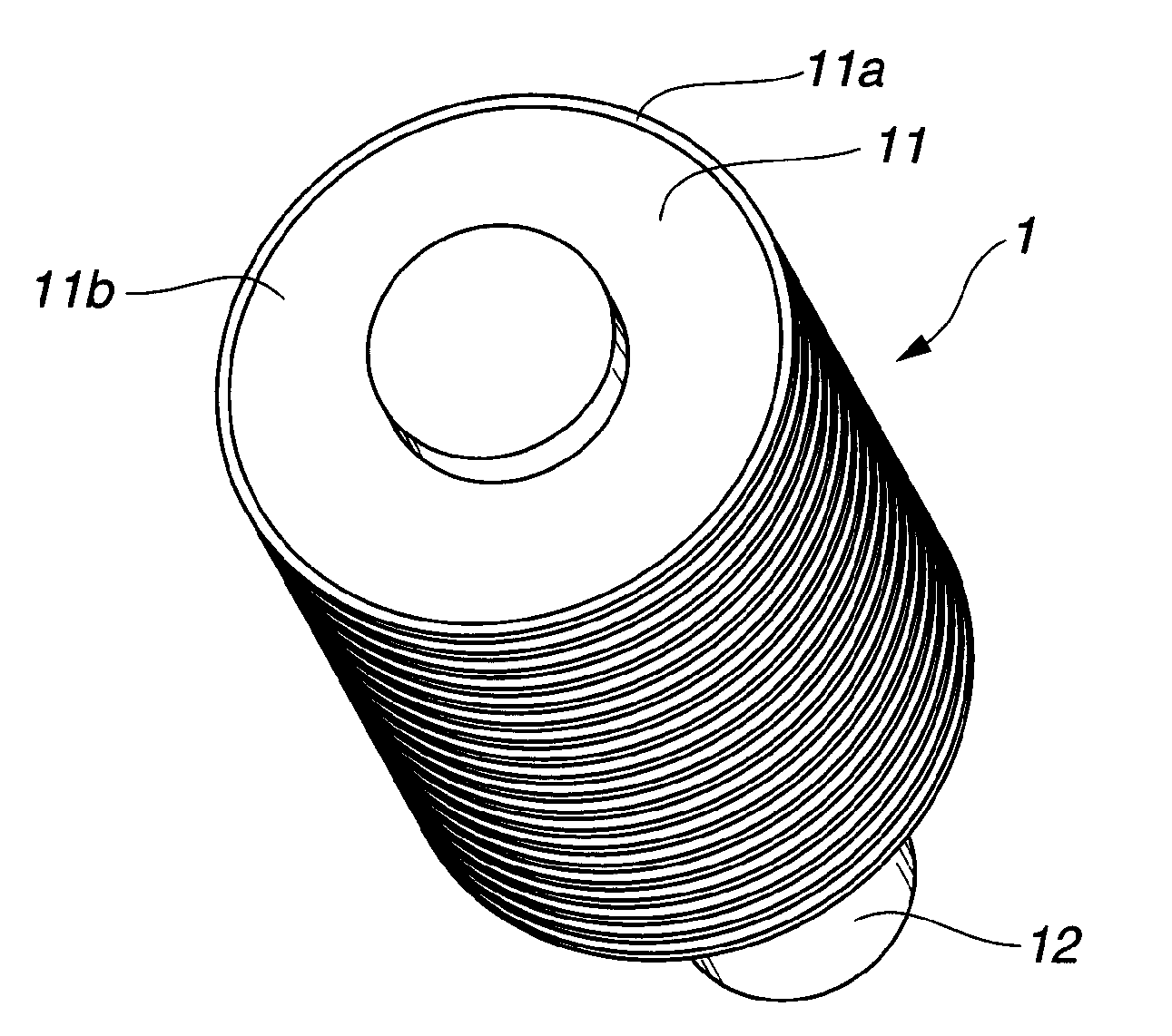
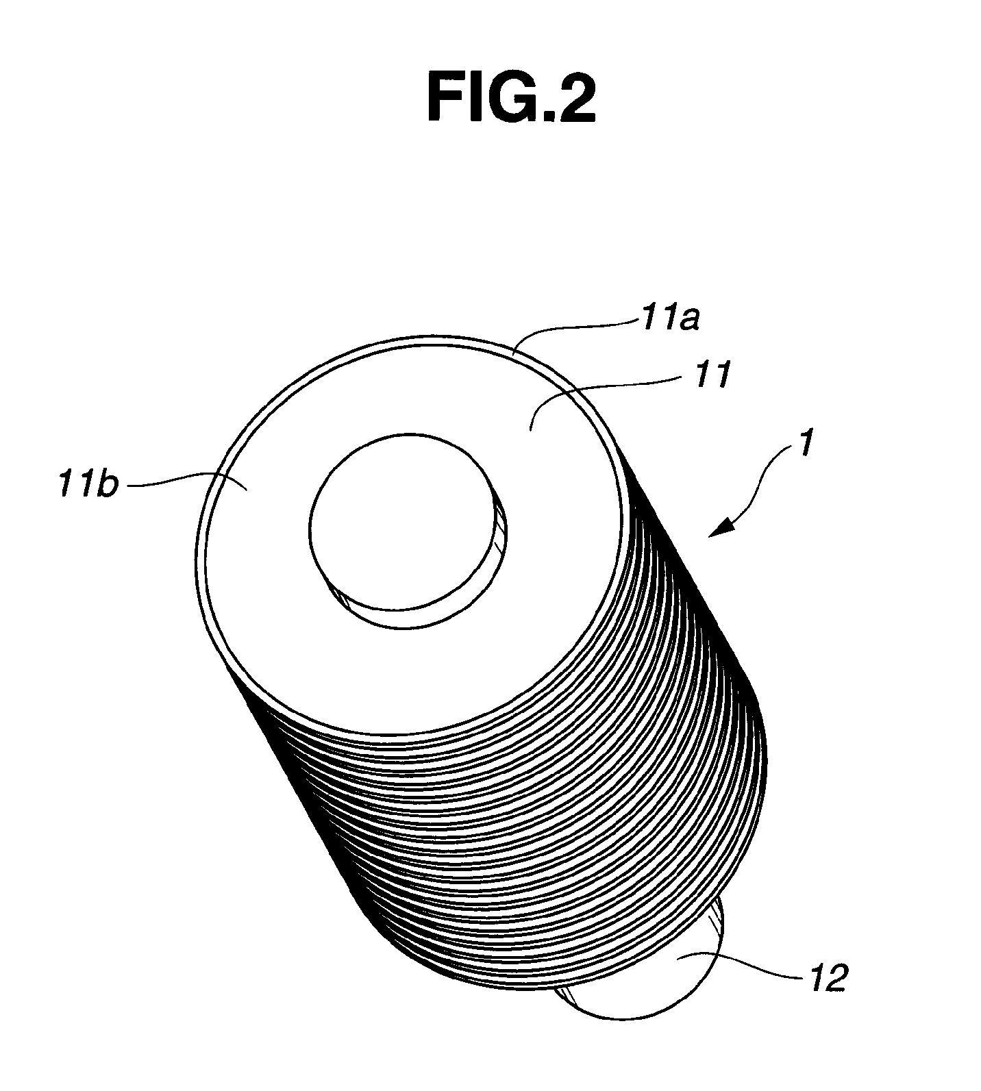
[0071]OD blades (cutoff abrasive blades) were fabricated by providing a doughnut-shaped disk core of cemented carbide (consisting of WC 90 wt % / Co 10 wt %) having an outer diameter 120 mm, inner diameter 40 mm, and thickness 0.3 mm, and bonding, by the resin bonding technique, artificial diamond abrasive grains to an outer peripheral rim of the core to form an abrasive section (peripheral cutting part) containing 25% by volume of diamond grains with an average particle size of 150 μm. The axial extension of the abrasive section from the core was 0.05 mm on each side, that is, the abrasive portion had a width of 0.4 mm (in the thickness direction of the core).

[0072]Using the OD blades, a cutting test was carried out on a workpiece which was a sintered Nd—Fe—B magnet block. The test conditions are as follows. A multiple blade assembly was manufactured by coaxially mounting 41 OD blades on a shaft at an axial spacing of 2.1 mm, with spacers interposed therebetween. The spacers each had...

example 2

[0084]OD blades (cutoff abrasive blades) were fabricated by providing a doughnut-shaped disk core of cemented carbide (consisting of WC 90 wt % / Co 10 wt %) having an outer diameter 115 mm, inner diameter 40 mm, and thickness 0.35 mm, and bonding, by the resin bonding technique, artificial diamond abrasive grains to an outer peripheral rim of the core to form an abrasive section (peripheral cutting part) containing 25% by volume of diamond grains with an average particle size of 150 μm. The axial extension of the abrasive section from the core was 0.025 mm on each side, that is, the abrasive portion had a width of 0.4 mm (in the thickness direction of the core).

[0085]Using the OD blades, a cutting test was carried out on a workpiece which was a sintered Nd—Fe—B magnet block. The test conditions are as follows. A multiple blade assembly was manufactured by coaxially mounting 42 OD blades on a shaft at an axial spacing of 2.1 mm, with spacers interposed therebetween. The spacers each h...

example 3

[0094]OD blades (cutoff abrasive blades) were fabricated by providing a doughnut-shaped disk core of cemented carbide (consisting of WC 90 wt % / Co 10 wt %) having an outer diameter 145 mm, inner diameter 40 mm, and thickness 0.5 mm, and bonding, by the resin bonding technique, artificial diamond abrasive grains to an outer peripheral rim of the core to form an abrasive section (peripheral cutting part) containing 25% by volume of diamond grains with an average particle size of 150 μm. The axial extension of the abrasive section from the core was 0.05 mm on each side, that is, the abrasive portion had a width of 0.6 mm (in the thickness direction of the core).

[0095]Using the OD blades, a cutting test was carried out on a workpiece which was a sintered Nd—Fe—B magnet block. The test conditions are as follows. A multiple blade assembly was manufactured by coaxially mounting 14 OD blades on a shaft at an axial spacing of 3.1 mm, with spacers interposed therebetween. The spacers each had...


PUM

PropertyMeasurementUnit
thicknessaaaaaaaaaa
thicknessaaaaaaaaaa
thicknessaaaaaaaaaa

Abstract

A rare earth magnet block is cutoff machined into pieces by rotating a plurality of cutoff abrasive blades. Improvements are made by starting the machining operation from the upper surface of the magnet block downward, interrupting the machining operation, turning the magnet block upside down, placing the magnet block such that the cutoff grooves formed before and after the upside-down turning may be aligned with each other, and restarting the machining operation from the upper surface of the upside-down magnet block downward until the cutoff grooves formed before and after the upside-down turning merge with each other.

Description

CROSS-REFERENCE TO RELATED APPLICATION[0001]This non-provisional application claims priority under 35 U.S.C. §119(a) on Patent Application No. 2010-136822 filed in Japan on Jun. 16, 2010, the entire contents of which are hereby incorporated by reference.TECHNICAL FIELD[0002]This invention relates to a method for cutoff machining a magnet block into multiple pieces.BACKGROUND ART[0003]Systems for manufacturing commercial products of rare earth magnet include a single part system wherein a part of substantially the same shape as the product is produced at the stage of press molding, and a multiple part system wherein once a large block is molded, it is divided into a plurality of parts by machining. These systems are schematically illustrated in FIG. 1. FIG. 1a illustrates the single part system including press molding, sintering or heat treating, and finishing steps. A molded part 101, a sintered or heat treated part 102, and a finished part (or product) 103 are substantially identic...

Claims


Application Information

Patent Timeline
Patent Type & Authority Applications(United States)
IPC IPC(8): B24B1/00B24B7/22B24B27/06
CPCB24B27/0076B24B27/0675H01F41/0253H01F1/0577B24D5/123B24B27/06B24B41/06B28D1/24B28D7/02
Inventor AKADA, KAZUHITOSATO, KOJIYOSHIMURA, NAOMICHI
Owner SHIN ETSU CHEM IND CO LTD
Why Eureka
Try Eureka