Optical system, optical element and optical device containing them

A technology of optical components and optical systems, applied in optical components, optics, instruments, etc., can solve problems such as large effective diameter, difficulty in correcting aberrations, and difficulty in reducing the size of optical components

Inactive Publication Date: 2005-10-12
CANON KK
View PDF3 Cites 0 Cited by
  • Summary
  • Abstract
  • Description
  • Claims
  • Application Information

AI Technical Summary

Problems solved by technology

[0018] Generally, in the case of the optical element shown in Figure 15, if the size of the intermediate imaging plane is large, that is, if the focal length of the first part B1 in Figure 16 is long, the effective diameter of the reflective surface behind the intermediate imaging plane becomes large and will make it difficult to reduce the size of the optics
If the size of the intermediate imaging plane is too small, i.e. if the focal length of the first part B1 is too short, it will be difficult to correct the aberrations formed by the optical surfaces behind the intermediate imaging plane

Method used


Image

  • Optical system, optical element and optical device containing them
  • Optical system, optical element and optical device containing them
  • Optical system, optical element and optical device containing them

Examples


Embodiment Construction

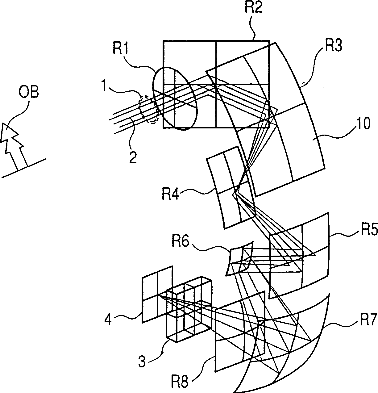
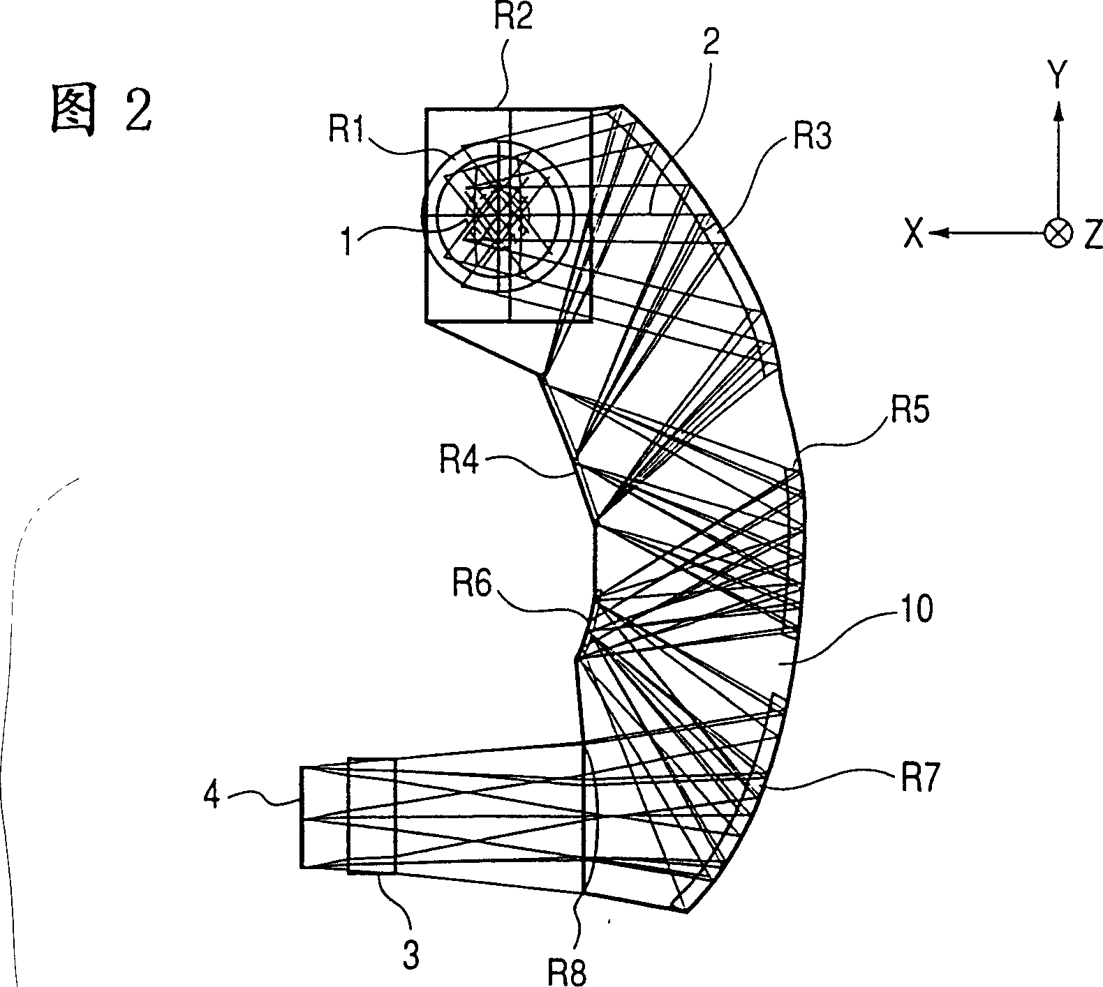
[0064] Before describing the embodiments of the present invention, how to express the specific structures of the embodiments and the problems common to all the embodiments will be described. Figure 14 It is a figure which schematically shows the coordinate system which defines the structural data of the optical system of this invention. In an embodiment of the present invention, the i-th surface is along the ray propagating from the object side to the imaging plane (it is formed by Figure 14 The ray represented by the chain line in and called the reference axis ray) is located on the i-th position of the surface. exist Figure 14 Among them, the first surface R1 is a diaphragm, the second surface R2 is a refractive surface coaxial with the first surface, the third surface R3 is a reflective surface inclined relative to the second surface R2, the fourth surface R4 and the fifth surface R5 are reflective surfaces offset and inclined relative to the surfaces in front of them,...


PUM


Abstract

An optical system has an aperture stop, and an optical unit placed on the image side of the aperture stop. The optical unit consists of the following components in the order named from the object side: a first optical component with a reflective curved surface, for forming an intermediate image of an object, a second optical component with a reflective curved surface, for forming an image of the aperture stop with light from the intermediate image of the object, and a third optical component with a reflective curved surface, for forming a secondary image of the object with light from the image of the aperture stop. When fB1(theta), fB2(theta), and fB3(theta) are focal lengths of the first optical component, the second optical component, and the third optical component, respectively, at an azimuth theta, the focal lengths satisfy the following conditions in the azimuth range of 00,fB2(theta)<0,fB3(theta)>0.

Description

technical field [0001] The present invention relates to an optical element, which is used in optical devices such as cameras, digital cameras, still picture cameras, copiers, etc., more specifically, relates to an optical element with imaging function, which is structurally Features multiple curved reflective surfaces. Background technique [0002] Various proposals have heretofore been made regarding reflective optical systems using reflective surfaces such as concave mirrors, convex mirrors, and the like. As an example of a reflective optical system, there is a Cassegrain reflector telescope called Cassegrain reflector telescope, which is used to reduce the total length of the optical system. The lens constitutes the optical path folding of the full-lens length telephoto lens system. [0003] As for the objective lens system of the telescope, besides the Cassegrain type for the same reason, there are various known types to reduce the overall length of the optical system ...

Claims


Application Information

Patent Timeline
Patent Type & Authority Patents(China)
IPC IPC(8): G02B27/00G02B17/08
CPCG02B17/086G02B17/0848G02B27/00
Inventor 须永敏弘
Owner CANON KK
Why Eureka
Try Eureka