Laser radar and working method thereof

A laser radar and laser beam technology, applied in the direction of radio wave measurement systems, instruments, etc., can solve the problems of large galvanometer rotation angle and small field of view, so as to improve accuracy, increase angular resolution and field of view, and reduce impact Effect

Active Publication Date: 2018-06-29
HESAI TECH CO LTD
View PDF3 Cites 41 Cited by
  • Summary
  • Abstract
  • Description
  • Claims
  • Application Information

AI Technical Summary

Problems solved by technology

[0004] However, LiDAR with MEMS micro-mirror has the disadvantage of small field of view or large galvanometer rotation angle

Method used


Image

  • Laser radar and working method thereof
  • Laser radar and working method thereof
  • Laser radar and working method thereof

Examples


Embodiment Construction

[0026] LiDAR has many problems, such as: the rotation angle of the galvanometer is large or the field of view of the LiDAR is small.

[0027] Combining with a kind of laser radar, analyze the reasons why the lidar field of view angle is small or the rotation angle of the galvanometer is large:

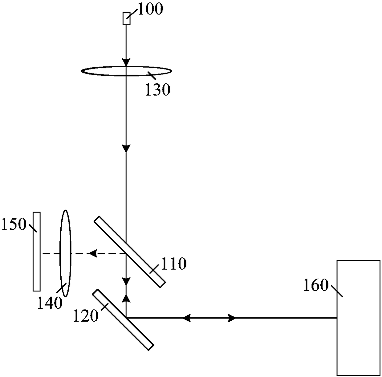
[0028] figure 1 It is a schematic diagram of the working principle of a laser radar.

[0029] The lidar includes: a laser 100, which is used to emit a laser beam; a collimating lens 130, which is used to collimate the laser beam 100 emitted by the laser 100; a vibrating mirror 120, which is used to change the Propagation direction; photoelectric detection array 150, used to receive the echo beam reflected by the target 160 to be detected; half-transparent mirror 110, used to transmit the laser beam 100 to the surface of the vibrating mirror 120, and enable the target to be detected The echo beam reflected by 160 is reflected into the photoelectric detection array 150 ;

[0030] Its ...


PUM


Abstract

The invention provides a laser radar and a working method thereof. The laser radar comprises a transmitting device, a beam splitting device, a galvanometer and a receiving device, wherein the transmitting device is used for transmitting a first laser beam to a to-be-detected object; the beam splitting device is used for splitting the first laser beam into a plurality of second laser beams, and thepropagation directions of the multiple second laser beams are different; the galvanometer comprises a first reflecting surface, the first reflecting surface is used for reflecting the second laser beams, the galvanometer is provided with a first rotary shaft and is rotated around the first rotary shaft, and an included angle between the first rotary shaft and a normal line of the first reflectingsurface is greater than zero; the receiving device is used for receiving echo beams reflected by the to-be-detected object. The laser radar has the advantage that the larger field angle can be obtained through smaller rotation angle of the galvanometer.

Description

technical field [0001] The invention relates to the technical field of semiconductor manufacturing, in particular to a laser radar and a working method thereof. Background technique [0002] Lidar is a commonly used ranging sensor, which has the characteristics of long detection distance, high resolution, and low environmental interference. It is widely used in intelligent robots, drones, unmanned driving and other fields. The working principle of lidar is similar to that of micron-wave radar, which uses the time it takes for light waves to travel between the radar and the target to evaluate the distance. [0003] Resolution and field of view are important indicators of lidar. In order to obtain high resolution, a multi-line lidar is proposed. The multi-line lidar adopts multiple emitters and corresponding detectors arranged in the vertical direction, which increases the detection range in the vertical direction. However, the space of multi-line lidar is limited, and too m...

Claims


Application Information

Patent Timeline
Patent Type & Authority Applications(China)
IPC IPC(8): G01S7/481
CPCG01S7/4817
Inventor 卢炎聪孙文婷向少卿李一帆
Owner HESAI TECH CO LTD
Why Eureka
Try Eureka