
X-ray diffraction apparatus and X-ray diffraction method

A diffraction device and X-ray technology, applied in measuring devices, material analysis using wave/particle radiation, instruments, etc., can solve the problem that X-ray detectors have complex structures, are difficult to apply X-ray diffraction methods, and cannot be used as X-ray beams and other problems, to achieve the effect of suppressing the reduction of X-ray intensity, suppressing the reduction of angular resolution, high angular resolution and X-ray intensity gain

Inactive Publication Date: 2009-04-08
RIGAKU CORP
View PDF3 Cites 15 Cited by
  • Summary
  • Abstract
  • Description
  • Claims
  • Application Information

AI Technical Summary

Problems solved by technology

[0008] As described in the above-mentioned first and second publications, the structure in which a plurality of crystal analyzers and a plurality of X-ray detectors are arranged around the sample is complex and expensive, and it is difficult to apply the X-ray diffraction method in a laboratory system.
[0009] As described in the above-mentioned 3rd publication, 4th publication, and 5th publication, a mirror having a reflective surface with a non-constant lattice plane interval cannot be used as a mirror with different incident angles in the parallel beam method. The use of mirrors where the X-ray beam is reflected towards different positions

Method used


Image

  • X-ray diffraction apparatus and X-ray diffraction method
  • X-ray diffraction apparatus and X-ray diffraction method
  • X-ray diffraction apparatus and X-ray diffraction method

Examples


Embodiment Construction

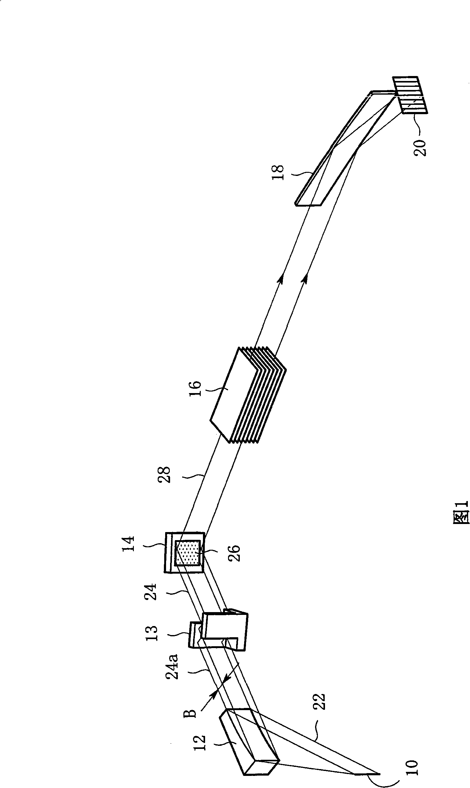
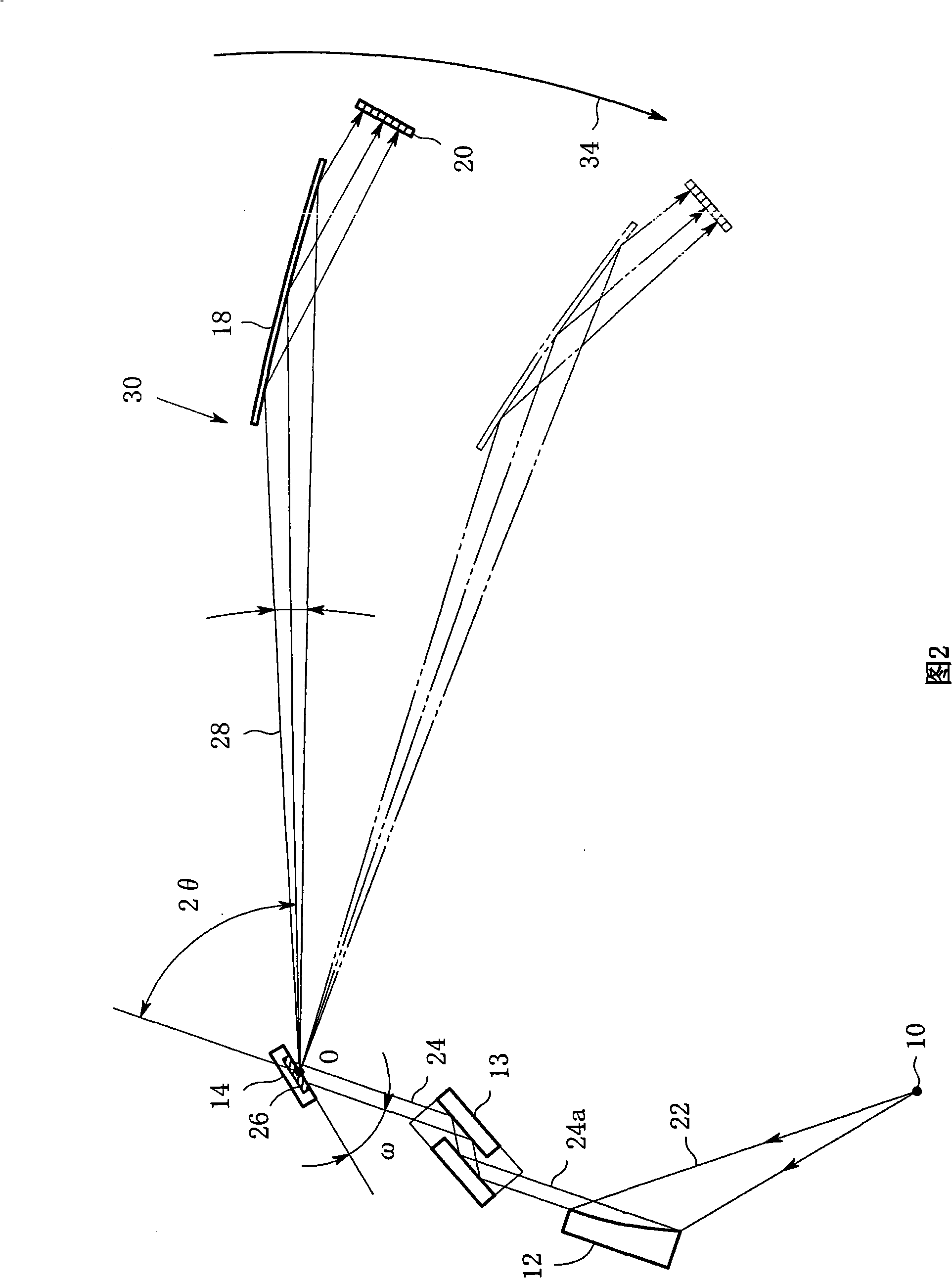
[0052] Hereinafter, embodiments of the present invention will be specifically described with reference to the drawings. Fig. 1 is a schematic perspective view of a first type of X-ray diffraction apparatus of the present invention. This X-ray diffraction device has: an X-ray source with a linear (or point-like) X-ray focus 10, a multilayer mirror (mirror) 12 with a parabolic reflective surface, and a channel cut for selecting the characteristic X-ray Kα1. Channel cut monochromator 13 (channel cut monochromometer), sample holder 14, Soller slit 16 (solar slit) to limit the longitudinal divergence of diffracted X-rays, mirror 18 composed of a crystal analyzer, and 1-dimensional position-sensitive X-rays detector 20. FIG. 1 shows the case where a linear X-ray focus is used. Although the X-rays emitted from the X-ray focal point 10 are divergent beams 22, the divergent beams 22 are converted into parallel beams 24a via the multilayer film mirror 12 having a parabola-shaped refle...


PUM

PropertyMeasurementUnit
lengthaaaaaaaaaa
lengthaaaaaaaaaa

Abstract

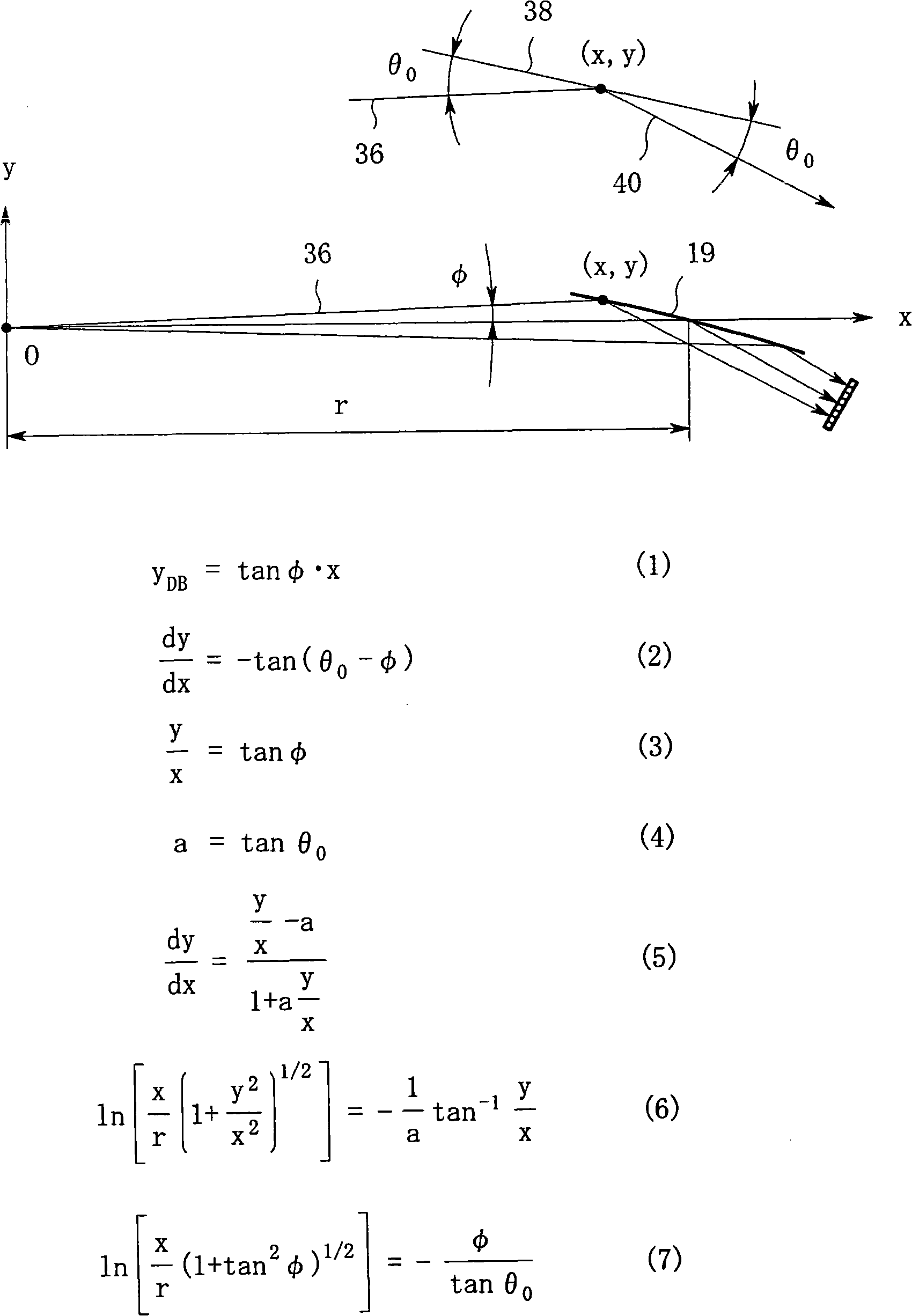
In an X-ray diffraction method using the parallel beam method, an X-ray parallel beam (24) is incident on a sample (26), and diffracted X-rays (28) from the sample (26) are reflected at a mirror (18) and thereafter detected by an X-ray detector (20). The reflective surface (19) of the mirror (18) has a shape of an equiangular spiral that has a center located on the surface of the sample (26). A crystal lattice plane that causes reflection is parallel to the reflective surface (19) at any point on the reflective surface (19). The X-ray detector (20) is one-dimensional position sensitive in a plane parallel to the diffraction plane. A relative positional relationship between the mirror (18) and the X-ray detector (20) is determined so that reflected X-rays (40) from different points on the reflective surface (19) of the mirror (18) reach different points on the X-ray detector (20) respectively. This X-ray diffraction method is superior in angular resolution, and is small in X-ray intensity reduction, and is simple in structure.

Description

technical field [0001] The invention relates to an X-ray diffraction device and an X-ray diffraction method using a parallel beam method. Background technique [0002] In the powder X-ray diffraction method of powder samples, thin film samples, and polycrystalline samples, when using the parallel beam method, in order to improve the angular resolution, it is necessary to insert analyzer. Such analyzers are known as long parallel slits with X-ray aperture angles and as crystal analyzers. If long parallel slits are used, the X-ray intensity will not be reduced too much, but the angular resolution will be reduced. On the other hand, crystal analyzers have a high angular resolution but significantly reduce the X-ray intensity. Therefore, in the parallel beam method, it is desirable to obtain an analyzer that can achieve high angular resolution and reduce X-ray intensity degradation. [0003] It is known in Journal of Synchrotron Radiation (1996), 3, 75-83 (hereinafter referr...

Claims


Application Information

Patent Timeline
Patent Type & Authority Applications(China)
IPC IPC(8): G01N23/207
Inventor 虎谷秀穗
Owner RIGAKU CORP
Learn More