Power-supply wiring device and harness layout structure by the power-supply wiring device

a technology of power-supply wiring and wiring device, which is applied in the direction of insulated conductors, cables, conductors, etc., can solve the problems of complicated motion of wire harnesses, increased manufacturing costs, and limited power-supply wiring devices. achieve the effect of smoothly absorbing the change of wire length

Inactive Publication Date: 2006-05-09
YAZAKI CORP
View PDF16 Cites 31 Cited by
  • Summary
  • Abstract
  • Description
  • Claims
  • Application Information

AI Technical Summary

Benefits of technology

[0030]According to the harness layout structure mentioned above, the harness holding member is moved together with the moving portion along a sliding direction and swung around the shaft. The harness holding member holds the wire harness without droop between the sliding structure and the fixed structure to prevent the wire harness from interference with the outside objects. When the sliding structure such as a sliding door is separated outwardly from the fixed structure such as a vehicle body and slid for opening completely, the harness holding member is drawn from the second case. When the sliding structure is slid and moved near to the fixed structure for closing completely, the harness hold...

Problems solved by technology

However, the aforesaid usual power-supply wiring devices are limited not to place the case at a position interfering with a window glass, a mechanism for moving the window glass up-and-down or electric devices in the sliding door.
When the sliding door is opened from complete closed condition, the sliding door is separated outwardly from the vehicle body and slid two-dimensionally, so that motion of the wire harness is complicated and the manufacturing cost may be increased by requiring a suitable flexible wire harness.
The power-supply wiring devices are required to use a leaf spring having high durability of bending, or an expensive electric wire cover having directional bending stiffness, so that the structure of the power-supply wiring device is complicated and the manufacturing cost is increased.
The wire harn...

Method used


Image

  • Power-supply wiring device and harness layout structure by the power-supply wiring device
  • Power-supply wiring device and harness layout structure by the power-supply wiring device
  • Power-supply wiring device and harness layout structure by the power-supply wiring device

Examples


Embodiment Construction

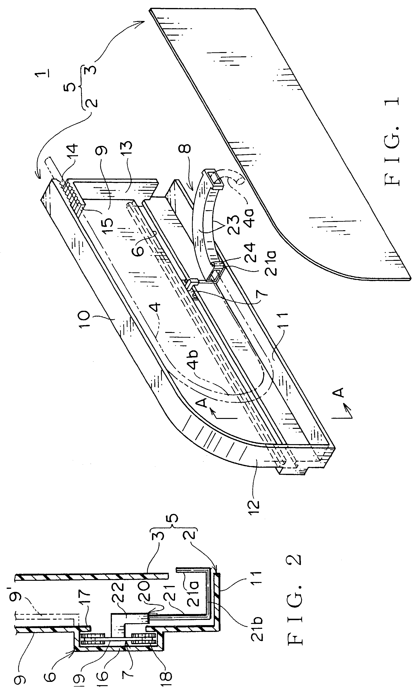
[0049]FIGS. 1–9 show each embodiment of a power-supply wiring device at a sliding door and harness layout structure with the power-supply wiring device according to the present invention.

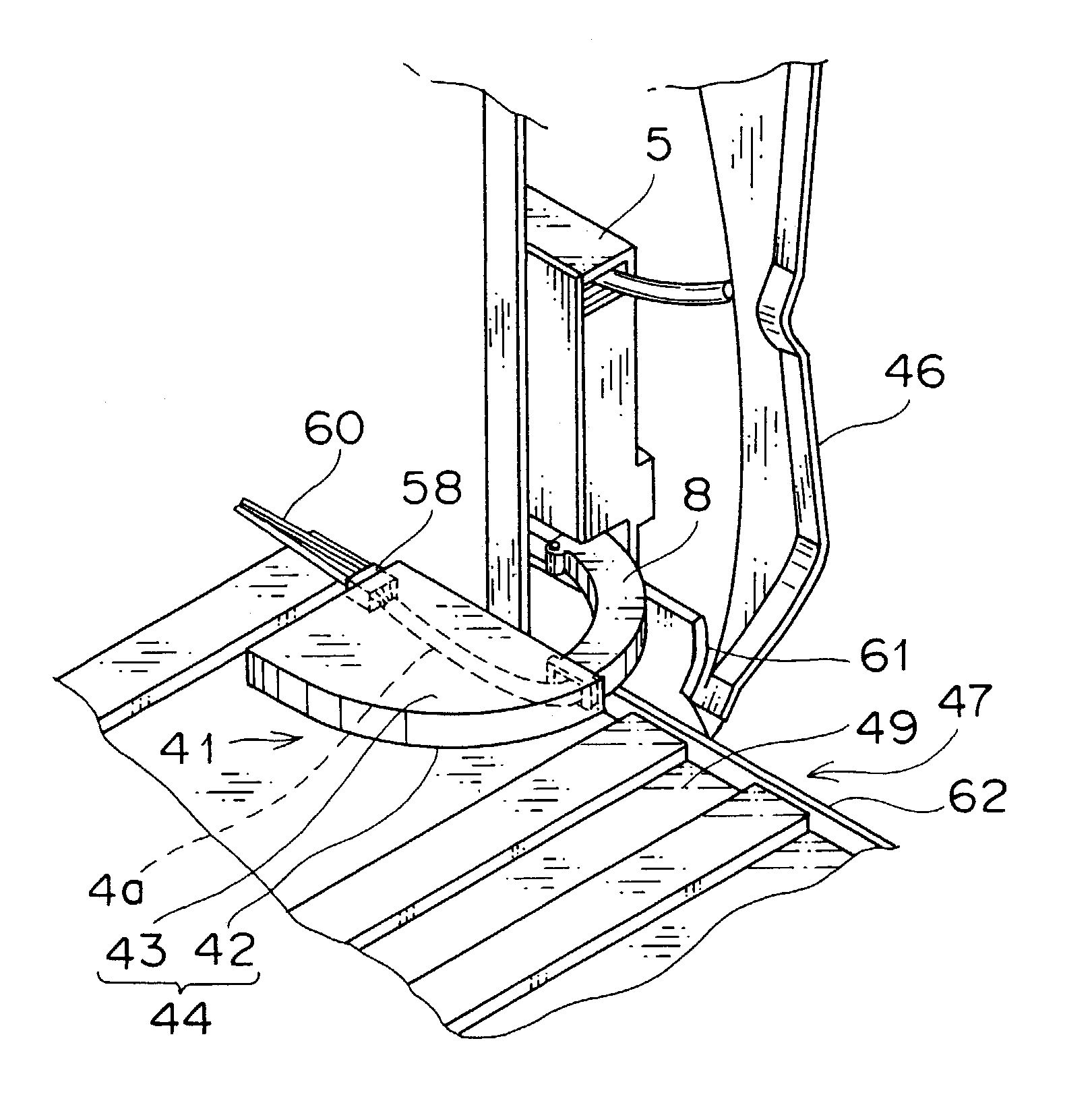
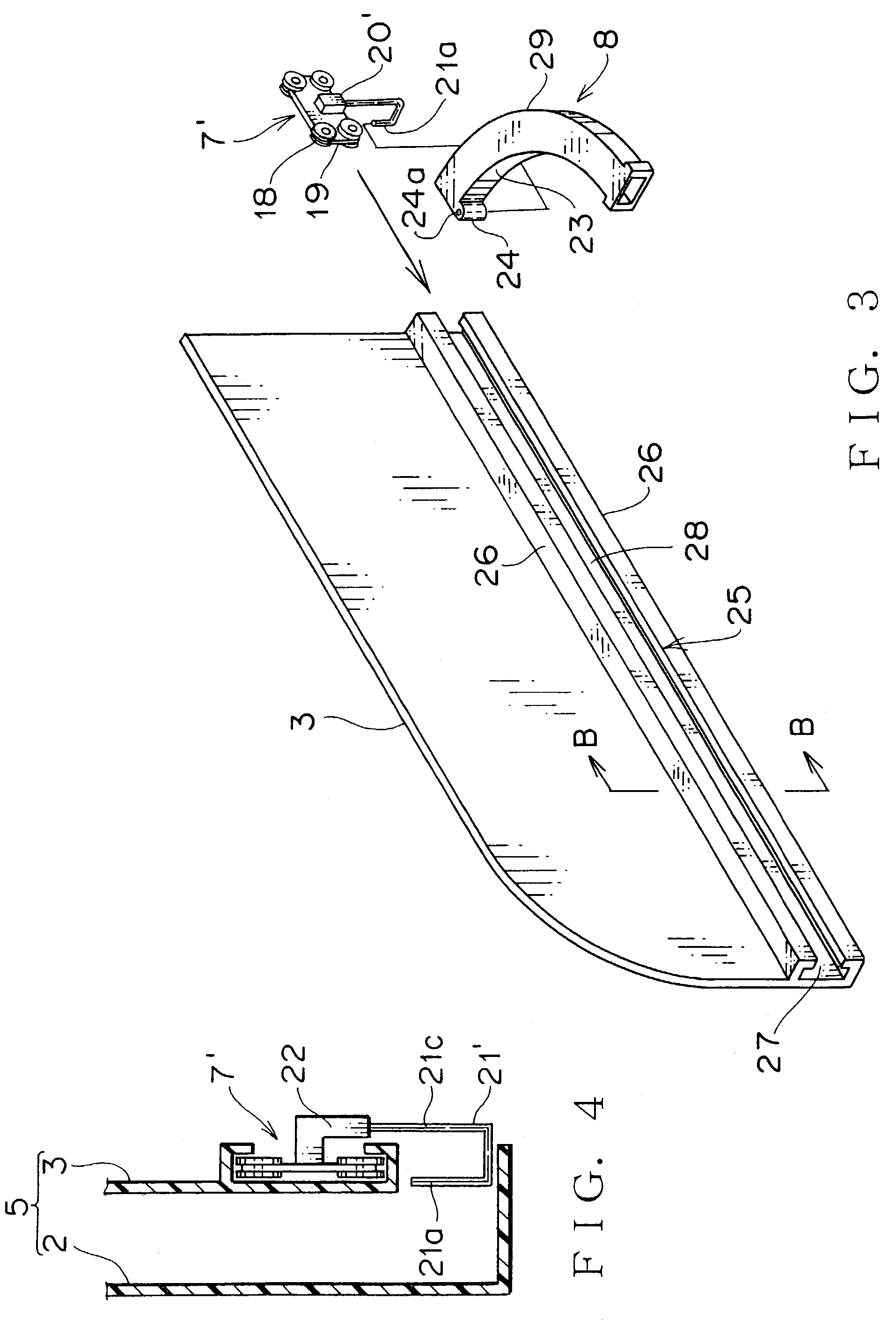
[0050]FIG. 1 shows the embodiment of the power-supply wiring device. The power-supply wiring device 1 includes a first case provided with a box-shape base portion 2 and a plate-shape cover 3 for receiving a wire harness 4 folded in a U-shape, a slider 7 (moving portion) engaging with a guide rail 6 (guide portion) of the base portion 2 freely to be slid to each other and a rectangular tubed harness holding member 8 supported by the slider 7 freely to be rotated for receiving a part of the wire harness 4a led from the first case 5.

[0051]The base portion 2 of the first case 5 has a vertical base plate 9, a surrounding wall having walls 10–13 perpendicular to the base plate 9 at top, bottom, right and left edges of the base plate 9, the horizontal guide rail 6 formed integrally with the base plate 9. T...


PUM


Abstract

A power-supply wiring device, which protects electric wires between a sliding and fixed structures, and absorbs wire length change by sliding motion of the sliding structure, and a harness layout structure with the power-supply wiring device are provided. The power-supply wiring device includes a first case 5 for receiving a wire harness 4 folded into a U-shape, a moving portion 7, a harness holding member 8 disposed rotatably at the moving portion 7, a second case 44 receiving the harness holding member 8 freely to be swung. In the harness layout structure, the first case 5 and the second case 44 are mounted respectively on the sliding structure and the fixed structure, and the harness holding member 8 connects between the fixed and sliding structures.

Description

BACKGROUND OF THE INVENTION[0001]1. Field of the Invention[0002]This invention relates to a power-supply wiring device, for example disposed in a sliding door of a car, to supply electric power continuously from a vehicle body to the sliding door with absorbing change of wire length between the sliding door and the vehicle body by a stroke to open and close the sliding door, and a harness layout structure by using the power-supply wiring device.[0003]2. Description of the Related Art[0004]Usually, to supply electric power from a vehicle body of a car to car electric devices or auxiliary devices in a sliding door, power-supply wiring device which pulls and pushes a wire harness in a case (harness protector) correspondingly to open / close motion of the sliding door. The case is mounted vertically in the sliding door, and the wire harness (electric wires covered by a protection tube of synthetic resin) is received with curvature in the case and pushed upwardly. One end of the wire harne...

Claims


Application Information

Patent Timeline
IPC IPC(8): H02B1/20B60R16/02
CPCB60R16/0215
Inventor TSUBAKI, AKIRA
Owner YAZAKI CORP
Why Eureka
Try Eureka