
Display rack with slidable member

a technology for displaying racks and objects, which is applied in the field of display racks with sliding members, can solve the problems of not being as presentable, items tend to slip, and the racks are not intended to be secured to slatwalls, pegboards or the lik

Inactive Publication Date: 2005-04-12
PIONEER PHOTO ALBUMS
View PDF34 Cites 14 Cited by
  • Summary
  • Abstract
  • Description
  • Claims
  • Application Information

AI Technical Summary

Benefits of technology

In accordance with another aspect of the present invention there is provided a display rack that includes a substantially horizontally oriented member having first and second opposite ends, a securing portion affixed to the second end of the substantially horizontally oriented member, and a carriage slidably engaged with the substantially horizontally oriented member. The securing portion including means for removably securing the rack to a substantially ...

Problems solved by technology

Retail stores have a limited amount of space in which to display products or present them for sale.
However, as consumers take the items off the rack, and the number of items on the rack decreases, the items tend to slip and are not as presentable as when in a vertical orientation.
However, none of these racks are intended to be secured to a slatwall, pegboard or the like.

Method used


Image

  • Display rack with slidable member
  • Display rack with slidable member
  • Display rack with slidable member

Examples


first embodiment

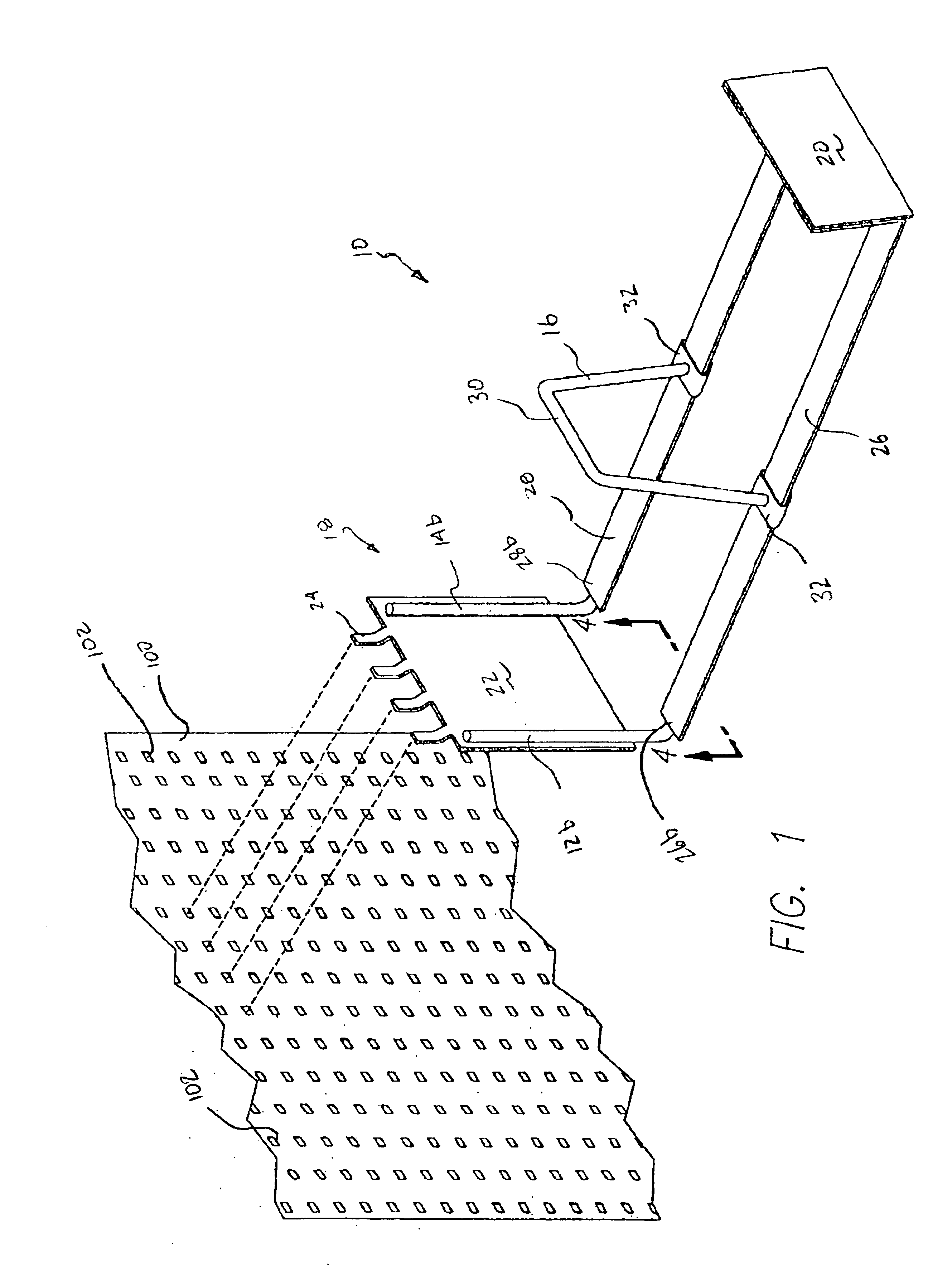
FIG. 1 is a perspective view of a display rack and a peg board in accordance with the present invention.

FIG. 2 is a top elevation of the display rack of FIG. 1.

FIG. 3 is a bottom elevation of the display rack of FIG. 1.

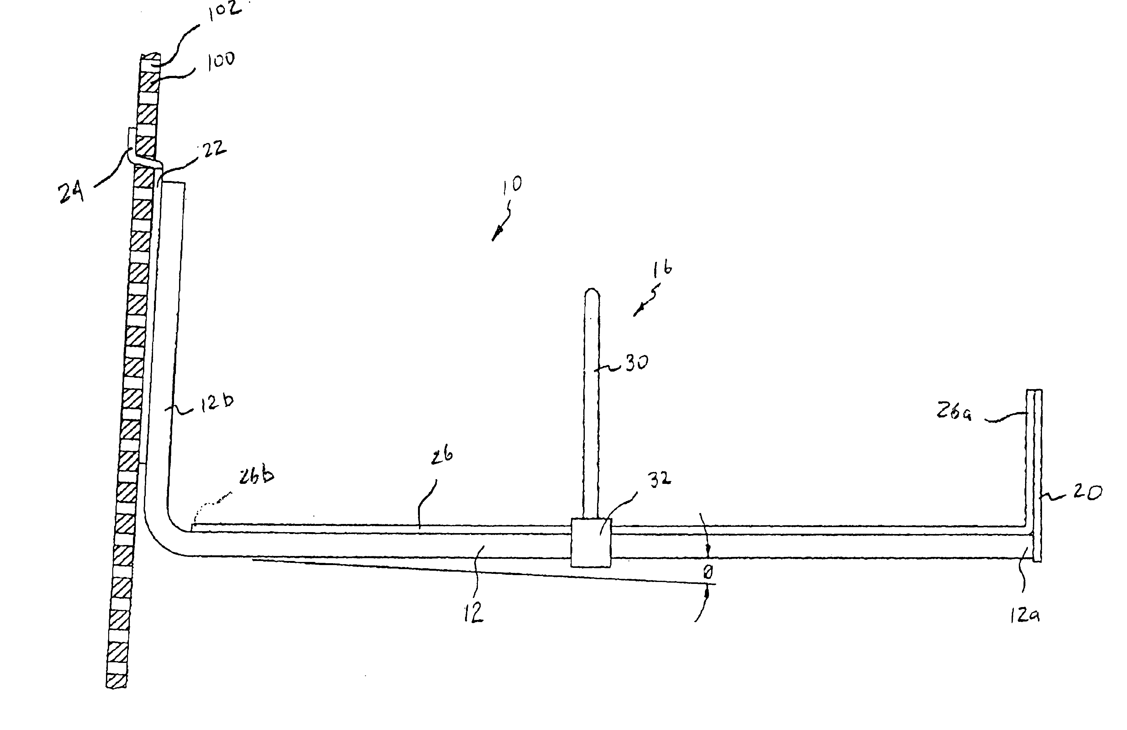
FIG. 4 is a rear elevation of the display rack of FIG. 1 with a portion of the display rack in section taken along line 4—4 of FIG. 1.

FIG. 5 is a side elevation of the display rack of FIG. 1 showing the angle θ.

second embodiment

FIG. 6 is a perspective view of a display rack and a peg board in accordance with the present invention.

FIG. 7 is a perspective view of a display rack removably secured to a peg board and having photo albums displayed thereon.

FIG. 8 is a perspective view of a display rack removably secured to a peg board and having photo albums displayed thereon, where one of the photo albums has begun to slip and is stopped by the carriage.

Like numerals refer to like parts throughout the several views of the drawings.


PUM


Abstract

A display rack including a pair of substantially horizontally oriented members in substantially parallel spaced relation, a stop member associated with the first ends of the pair of substantially horizontally oriented members, a securing portion affixed to the second ends of the pair of substantially horizontally oriented members, and a carriage. The substantially horizontally oriented members each have first and second ends, the second ends of which are turned upwardly. The securing portion has at least one peg hook extending upwardly and rearwardly therefrom. The carriage includes a middle portion extending between and above the pair of substantially horizontally oriented members and a pair of engagement members that slidingly engage the pair of substantially horizontally oriented members.

Description

FIELD OF THE INVENTIONThe present invention relates to a rack for displaying objects, and more particularly to a rack for displaying objects having a slidable member for holding the objects in place.BACKGROUND OF THE INVENTIONRetail stores have a limited amount of space in which to display products or present them for sale. Many products are presented for sale by placing them on shelves, racks or the like. Racks having parallel rods that extend outwardly from a slatwall, pegboard or the like are known. These racks are used for selling items, such as photo albums, by placing a stack of items back to front in a vertical orientation on the parallel rods. However, as consumers take the items off the rack, and the number of items on the rack decreases, the items tend to slip and are not as presentable as when in a vertical orientation.It is desirable to include a slidable member on the rack that holds the items in place. Devices that include parallel rods having slidable members thereon ...

Claims


Application Information

Patent Timeline
IPC IPC(8): A47F5/08
CPCA47F5/083
Inventor PLUTSKY, SHELDON
Owner PIONEER PHOTO ALBUMS
Features
  • Generate Ideas
  • Intellectual Property
  • Life Sciences
  • Materials
  • Tech Scout
  • Unparalleled Data Quality
  • Higher Quality Content
  • 60% Fewer Hallucinations
Learn More