Directional lock

a directional lock and lock body technology, applied in the direction of bedstands, manufacturing tools, transportation and packaging, etc., can solve the problems of large footprint, relatively high cost, and complicated known directional locks

Inactive Publication Date: 2005-04-19
SPAN MEDICAL PROD CANADA
View PDF44 Cites 75 Cited by
  • Summary
  • Abstract
  • Description
  • Claims
  • Application Information

AI Technical Summary

Benefits of technology

[0015]In another alternative aspect, there is provided an adjustable bed having a primary frame for supporting a mattress frame, a first pair of leg assemblies coupled to the primary frame at a foot end of the primary frame, and a second pair of leg assemblies coupled to the primary frame at the head end thereof. The first pair of leg assemblies and the second pair of leg assembles are adapted to cooperate to support the primary frame above a floor surface and to move the primary frame relative to the floor surface. The first pair of leg assemblies includes a pair of legs, a chassis element, and a pair of follower bars. Each leg has a proximal end pivotally coupled to the primary frame, and a distal end pivotally coupled to the chassis element and spacing the chassis element apart from the primary frame. Each follower bar is pivotally coupled to the primary frame at a first end thereof and pivotally coupled to the chassis element at a second end thereof. The first end of each follower bar and the proximal end of each leg are spaced apart a first predetermined distance in substantially vertical relation to each other. Also, the second end of each follower bar and the proximal end of each leg are spaced apart a second predetermined distance in substantially vertical relation to each other. In addition, the first predetermined distance and the second predetermined distance are substantially the same. Each leg and each follower bar respectively cooperate with each other to maintain the chassis element in a substantially vertical position as the primary frame is moved relative to the floor surface. The adjustable bed includes casters with stems secured in the chassis elements of the first leg assemblies. Also, the adjustable bed includes directional locks positioned adjacent to the casters respectively, so that each directional lock's engagement portion is engageable with each respective caster's wheel assembly.

Problems solved by technology

In known adjustable beds, the horizontal movement of the casters or rollers on the floor surface resulting from vertical movement of the frame tends to result in simultaneous limited horizontal movement of the frame as well, as is well known in the art.
However, in known adjustable beds, the footprint tends to be larger than the bed frame due to horizontal movement of the frame during its vertical movement.
However, known directional locks typically include a mechanism inside a caster housing for controlling the direction of travel of the wheel assembly, so that the known directional locks are usually somewhat complex and relatively expensive.

Method used


Image

  • Directional lock
  • Directional lock
  • Directional lock

Examples


Embodiment Construction

)

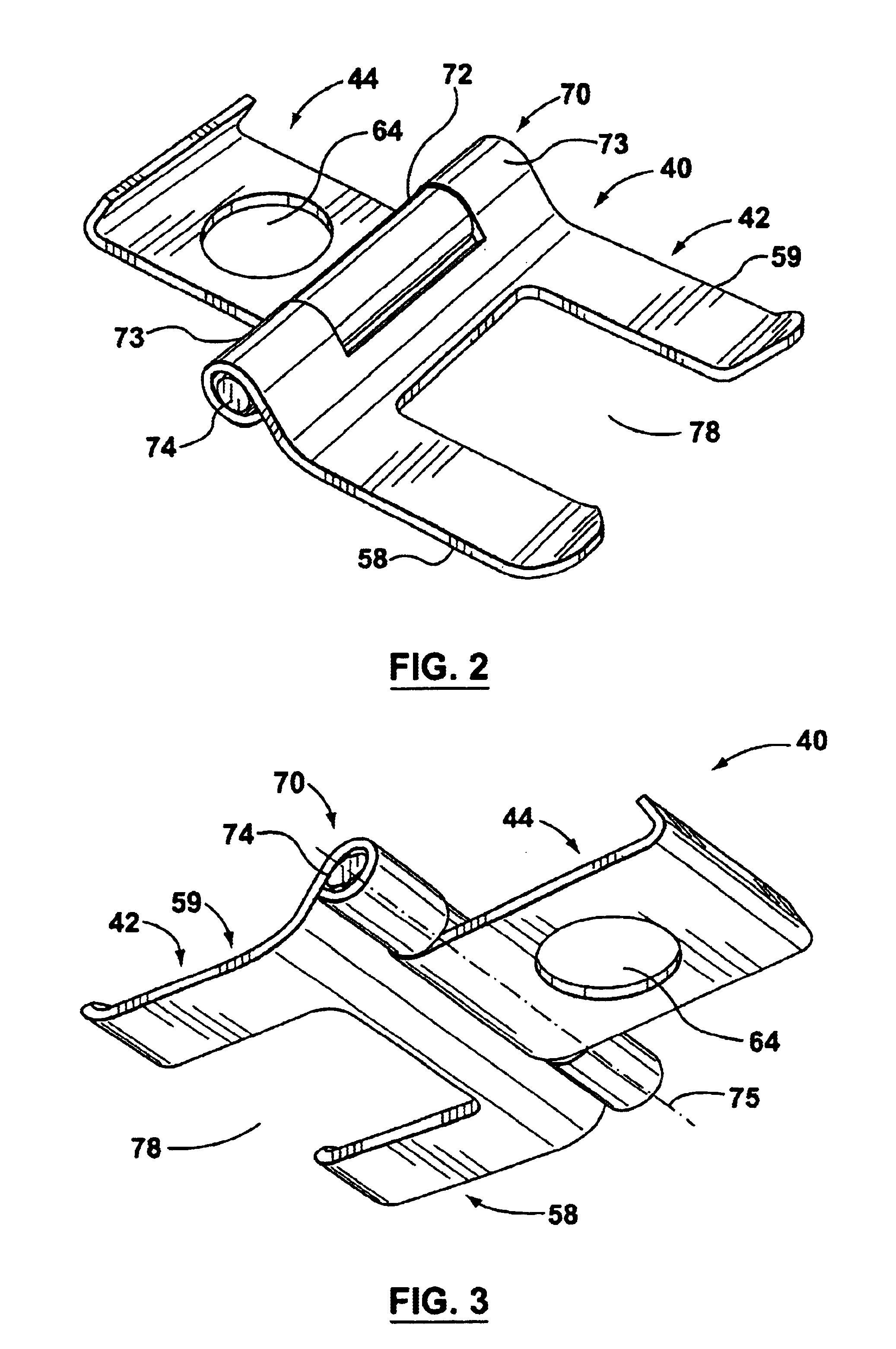
[0041]Reference is first made to FIGS. 2-9 to describe a preferred embodiment of a directional lock indicated generally by the numeral 40 in accordance with the invention. As can be seen in FIGS. 2-5, the directional lock 40 includes an engagement portion 42 and a base portion 44 coupled to the engagement portion 42 so that the engagement portion 42 is movable relative to the base portion 44, as will be described.

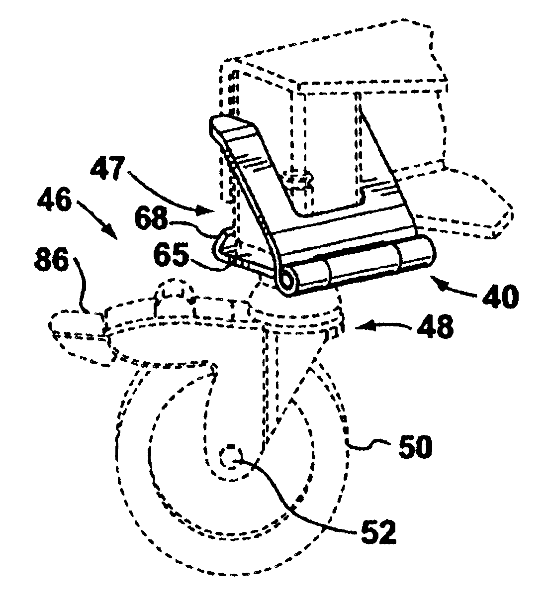
[0042]The directional lock 40 is shown in FIGS. 6-9 with a caster 46 and a chassis element 47, the caster 46 and the chassis element 47 being shown in dashed lines. The caster 46 has a wheel assembly 48 including a wheel 50 rotatable about a wheel axle 52 (FIG. 6) defining a wheel axis 53 (FIG. 8), as is known in the art. Also, the wheel assembly 48 includes a housing 54 for supporting the wheel axle 52. As is known in the art, the housing 54 defines a cavity for receiving a portion of the wheel 50. The caster 46 also includes a stem 56, and the wheel assembly 48 is pivota...


PUM


Abstract

A directional lock for a caster. The caster has a wheel assembly including a wheel rotatable about a wheel axis and a housing for supporting the wheel. The housing defines a cavity for receiving a portion of the wheel. Also, the caster includes a stem supported by the housing and positionable in a chassis element, the wheel assembly being pivotally attached to the stem. The directional lock has an engagement portion and a base portion coupled to the engagement portion such that the engagement portion is movable relative to the base portion. The engagement portion is for engaging the wheel assembly to locate the wheel assembly in a predetermined position relative to the chassis element. The base portion is adapted to cooperate with the chassis element to maintain the engagement portion in a predetermined relation to the chassis element.

Description

FIELD OF THE INVENTION[0001]This invention relates to directional locks for casters and, more particularly, directional locks for casters on an adjustable bed.BACKGROUND OF THE INVENTION[0002]The use of casters to facilitate the movement of equipment, for example, on adjustable beds for use in long-term care facilities or hospitals, is known. An typical adjustable bed includes a frame supported by legs. In a conventional adjustable bed, movement of the legs causes movement of the frame relative to a floor surface supporting the bed. The frame holds a mattress support on which a mattress is placed. Typical adjustable beds are disclosed in U.S. Pat. No. 4,097,939 (Peck et al.) and U.S. Pat. No. 6,230,344 (Thompson et al.).[0003]The conventional adjustable bed extends between a head end and a foot end, and the legs extending towards the floor surface at the head end are typically supported above the floor surface by casters or rollers. For example, Thompson at al. discloses an adjustab...

Claims


Application Information

Patent Timeline
Patent Type & Authority Patents(United States)
IPC IPC(8): A47C19/00A47C19/02A61G7/012A61G7/002B60B33/02B60B33/00A61G7/05
CPCA47C19/024B60B33/0002B60B33/0005B60B33/0018B60B33/0039B60B33/0049B60B33/0057B60B33/0068B60B33/0073B60B33/0081B60B33/021B60B33/025A61G7/012Y10T16/18A61G2007/0528A61G7/0506Y10T16/195A61G7/0528
Inventor THOMPSON, RALPHRUTHERFORD, GEOFFFREEBORN, BRIAN
Owner SPAN MEDICAL PROD CANADA
Why Eureka
Try Eureka