Portable workbench having collapsible support structure

a workbench and support structure technology, applied in the field of workbench, can solve the problems of cumbersome and otherwise awkward manipulation of the workbench having a collapsible featur

Inactive Publication Date: 2005-04-26
BLACK & DECKER INC
View PDF67 Cites 26 Cited by
  • Summary
  • Abstract
  • Description
  • Claims
  • Application Information

AI Technical Summary

Problems solved by technology

Often, workbenches having a collapsible feature a

Method used


Image

  • Portable workbench having collapsible support structure
  • Portable workbench having collapsible support structure
  • Portable workbench having collapsible support structure

Examples


Embodiment Construction

[0020]The following description of the preferred embodiment(s) is merely exemplary in nature and is in no way intended to limit the invention, its application, or uses.

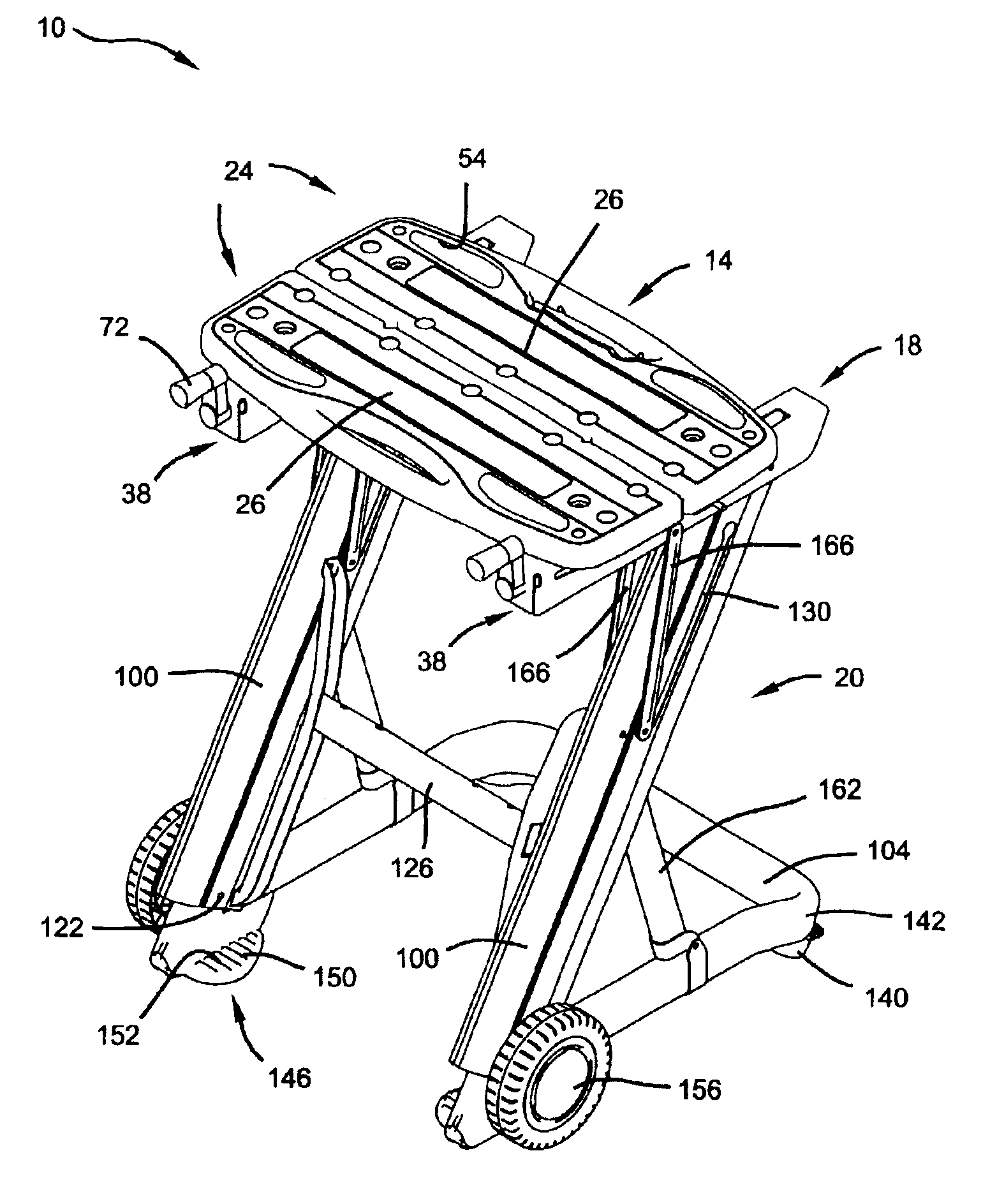
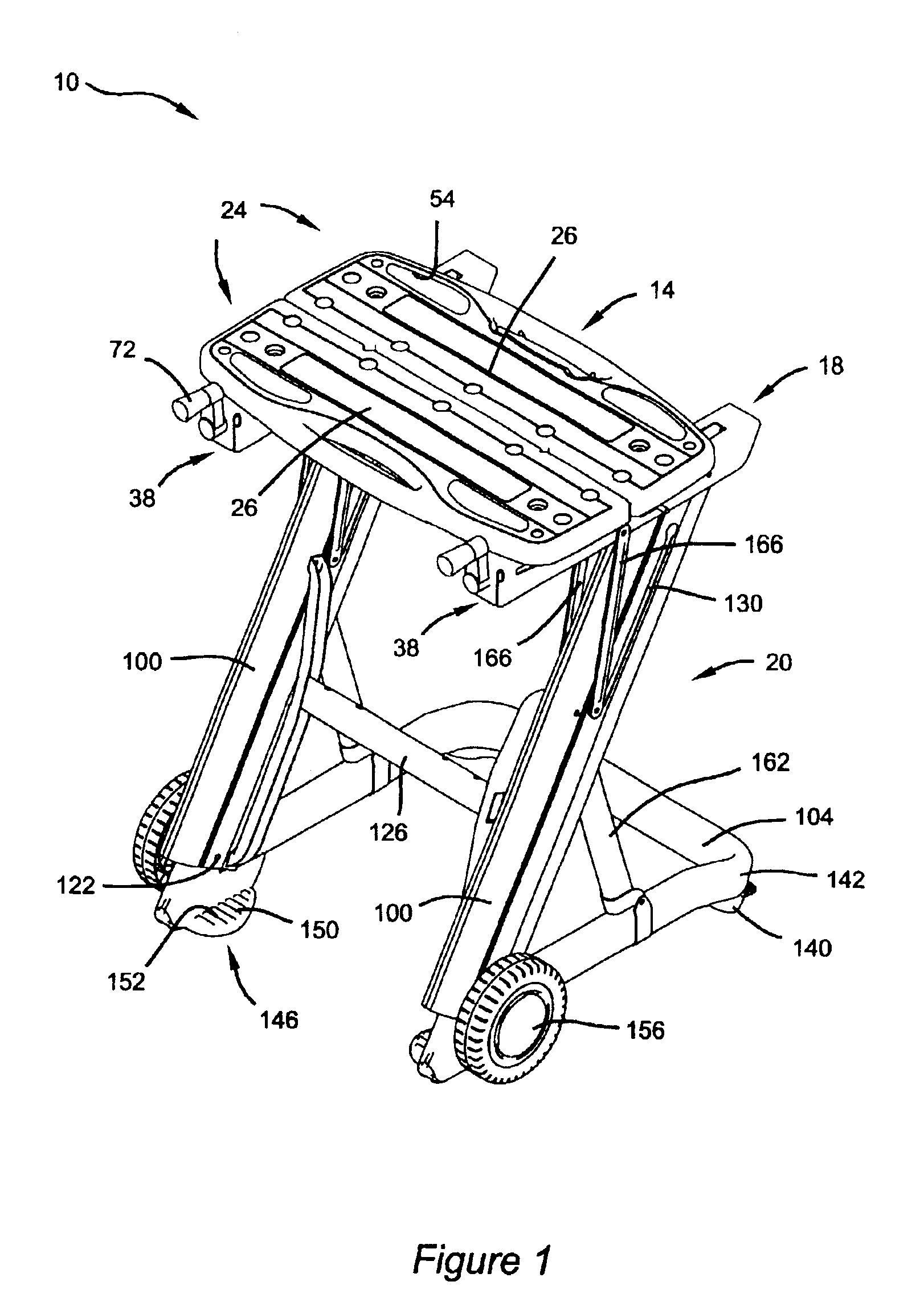
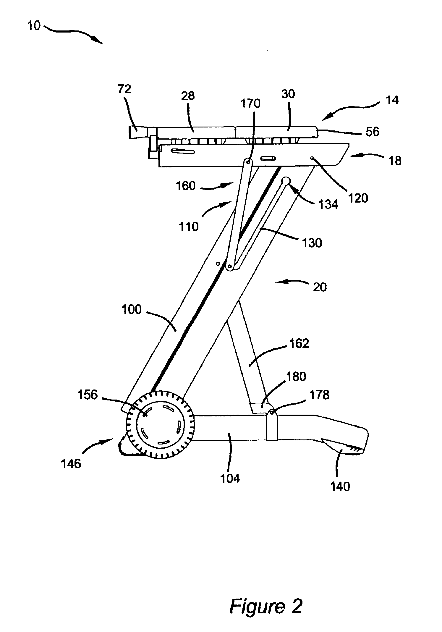
[0021]With initial reference to FIGS. 1-4, a portable workbench 10 according to the present invention is shown. Workbench 10 generally includes a top structure 14, a support structure 18 and a collapsible frame 20. Workbench 10 is movable between an expanded position, as shown in FIG. 1, and a collapsed position, as shown in FIG. 3.

[0022]With continued reference to FIGS. 1-4 and further reference to FIGS. 5 and 6, top structure 14 will be described in greater detail. Top structure 14 includes a pair of elongated mutually adjacent top members 24 including upper work supporting surfaces 26 lying generally in a common plane. Top members 24 are further defined by stationary member 28 and translating member 30. Top members 24 include longitudinally extending opposed side portions 36 defining clamping surfaces. As will be d...


PUM


Abstract

A portable workbench includes a top structure, a support structure and a collapsible frame. The top structure includes upper work supporting surfaces lying in a common plane and longitudinally extending opposed side portions defining clamping surfaces. A linkage mechanism cooperates with the frame to actuate the workbench between an expanded working position and a collapsed transport position. A lever releasably cooperates with the frame to maintain the workbench in a locked expanded position.

Description

FIELD OF THE INVENTION[0001]The present invention relates to a workbench and more specifically to a collapsible portable workbench.BACKGROUND OF THE INVENTION[0002]Workbenches incorporating a workpiece clamping device provide a convenient structure to secure a workpiece while performing a tooling operation. This type of clamping workbench generally includes a pair of top members, one of which is fixed to a supporting structure, while the other is adjustable along the supporting structure toward and away from the first one of the top members by a screw-type handle translation device.[0003]Certain workbenches of this type include removable base assemblies for transportation and storage purposes while others incorporate an integrated collapsible supporting structure. Often, workbenches having a collapsible feature are cumbersome and otherwise awkward to manipulate.[0004]While the above described arrangement has proven to be successful, a need has arisen for a more simple portable workb...

Claims


Application Information

Patent Timeline
IPC IPC(8): B25B1/10B25B1/00B25B1/02B25H1/10B25H1/02B25H1/04B25H1/00B25H1/14
CPCB25H1/04
Inventor FORTIN, MARC A.MASON, JOHN BRYANSIROIS, MIKE G.WATTERS, ROBERT D.READ, CLIFFORD D.
Owner BLACK & DECKER INC
Why Eureka
Try Eureka