Front release for a slide assembly

a slide assembly and front release technology, applied in the field of slide assemblies, can solve the problems of inconvenient lockout, difficult, or even impossible, and achieve the effect of reducing the number of slide assemblies

Inactive Publication Date: 2005-04-26
JONATHAN ENGINEERED SOLUTIONS
View PDF26 Cites 27 Cited by
  • Summary
  • Abstract
  • Description
  • Claims
  • Application Information

AI Technical Summary

Benefits of technology

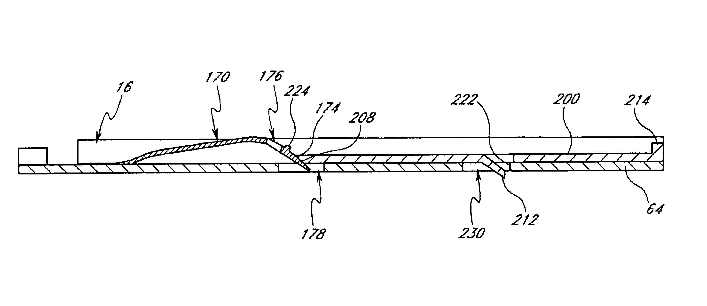
[0019]An elongated release member is slidably disposed within the channel of the load-carrying member such that a first end is adjacent to the lock arm lip and a second end is adjacent to an outward end of the load-carrying member. The elongated release member is translated inwardly to cause the elongated release member first end to depress the lock arm lip thereby elastically deforming the lock arm such that the lock arm window moves away from the protrusion thereby allowing relative movement of the intermediate member and the load-carrying member.

Problems solved by technology

This is an inconvenient lock-out mechanism location when attempting to release and retract the server computer.
This can be difficult, or even impossible, appreciating that the slide assemblies are usually mounted on opposing sides of the server, and a technician must simultaneously reach both lock-out mechanisms.
Moreover, once actuated, many lock-out mechanisms do not maintain a disengaged state and are biased to return to a locked state if the manual actuation is released before the load-carrying segment begins retracting into a preceding slide segment.

Method used


Image

  • Front release for a slide assembly
  • Front release for a slide assembly
  • Front release for a slide assembly

Examples


Embodiment Construction

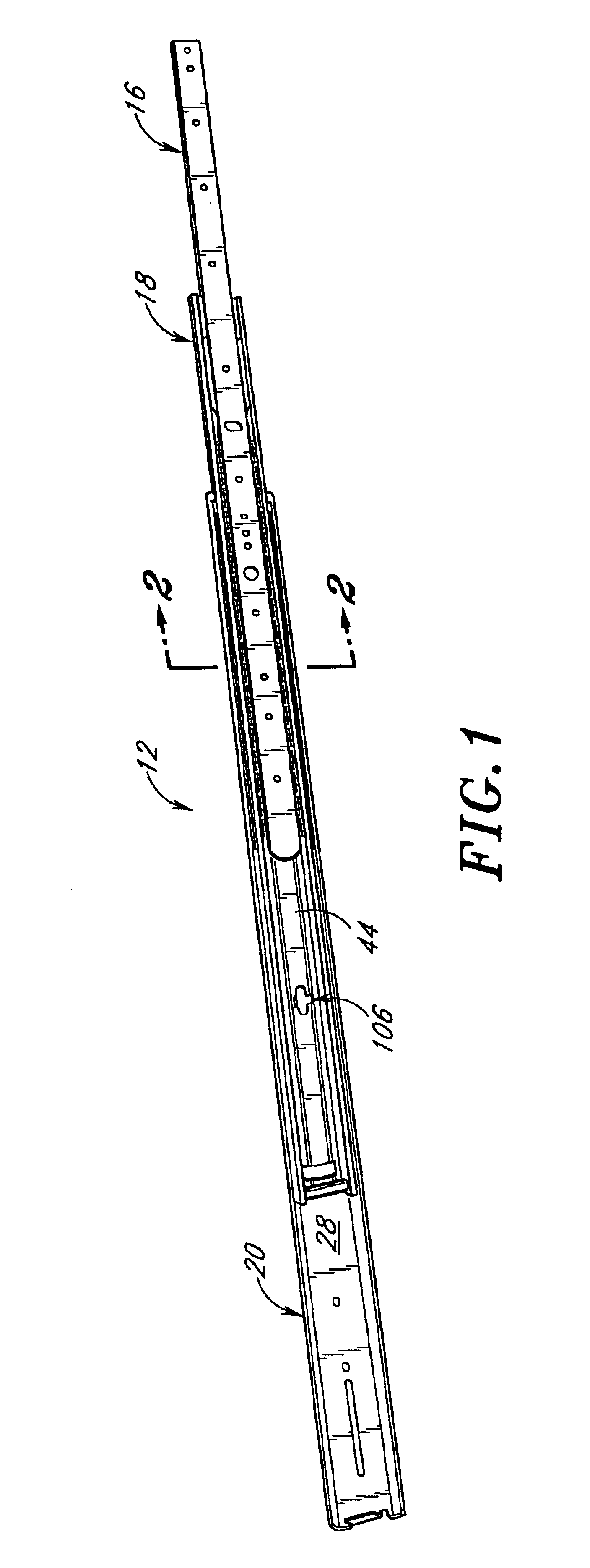
[0061]A slide assembly having features in accordance with the present invention is illustrated in FIG. 1 and designated generally by the reference numeral 12. In the embodiment illustrated in FIG. 1, the slide assembly 12 includes a first or inner slide segment 16, a second or intermediate slide segment 18, and a third or outer slide segment 20. The inner slide segment 16 is adapted for mounting to an outer case or housing of a computer server (not shown). The outer slide segment 20 is adapted for mounting to a stationary server rack structure (not shown). Each computer server desirably is supported in the server rack structure by a pair of slide assemblies 12, one on either side of the computer server, to allow the computer server to slide in and out of the server rack structure.

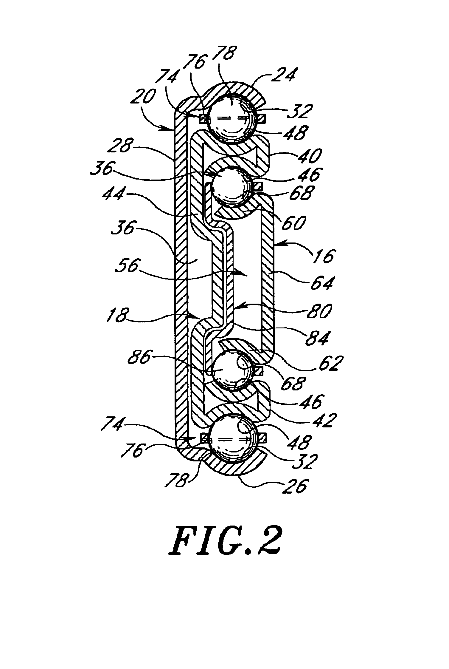
[0062]FIG. 2 is a cross-sectional view of the slide assembly 12 of FIG. 1, taken along the line 2—2 of FIG. 1. With reference to FIGS. 1 and 2, the outer slide segment 20 has a generally C-shaped cross-sect...


PUM


Abstract

A slide assembly is provided comprising a stationary slide segment, an intermediate slide segment, and a load-carrying slide segment. A bearing assembly is provided between the segments to reduce the friction therebetween. A lock arm extends from the load-carrying slide segment and is engageable with an engagement surface of the intermediate slide segment to limit movement of the load-carrying slide segment with respect to the intermediate slide segment when the load-carrying slide segment is fully extended. An elongated release member is slidably disposed within the channel of the load-carrying member, and as the release member is displaced inwardly, it depresses the lock arm thereby actuating the release mechanism by disengaging the lock arm from the engagement surface. The release mechanism remains actuated until the load-carrying slide segment is fully inserted into the intermediate slide member.

Description

RELATED APPLICATION[0001]This application is a continuation-in-part of U.S. application Ser. No. 10 / 028,030, filed Dec. 19, 2001, now U.S. Pat. No. 6,655,763, which is hereby expressly incorporated by reference in its entirety.BACKGROUND OF THE INVENTION[0002]1. Field of the Invention[0003]The present invention relates to slide assemblies and, more particularly, to a front release mechanism for a slide assembly.[0004]2. Description of the Related Art[0005]Computer servers for computer systems are often mounted in rack structures for convenience and to conserve floor space. Typically, several computer servers are spaced vertically and mounted in each rack structure. To facilitate access to the individual servers for maintenance or upgrades, each server is typically mounted on a pair of slide assemblies to allow the server to slide into and out of the rack structure.[0006]Typical slide assemblies comprise two or more telescoping slide segments. An outer or stationary slide segment is ...

Claims


Application Information

Patent Timeline
Patent Type & Authority Patents(United States)
IPC IPC(8): A47B88/04A47B88/10H05K7/14A47B88/493
CPCA47B88/10H05K7/1421A47B2088/0444A47B2210/0016A47B2210/0059A47B2210/0081A47B2210/0032A47B2088/4235A47B88/493H05K7/1489
Inventor JUDGE, RONALD JOHNYOUNG, JOHN NAN-HENGCIROCCO, PAUL
Owner JONATHAN ENGINEERED SOLUTIONS
Why Eureka
Try Eureka