
Variable delay element for use in delay tuning of integrated circuits

a technology of delay tuning and delay element, which is applied in the direction of pulse manipulation, pulse technique, electrical apparatus, etc., can solve the problem of imposing an incremental delay on the input signal by each stag

Inactive Publication Date: 2005-04-26
INTEL CORP
View PDF7 Cites 8 Cited by
  • Summary
  • Abstract
  • Description
  • Claims
  • Application Information

AI Technical Summary

Problems solved by technology

Each stage imposes an incremental delay upon the input signal when enabled.

Method used


Image

  • Variable delay element for use in delay tuning of integrated circuits
  • Variable delay element for use in delay tuning of integrated circuits
  • Variable delay element for use in delay tuning of integrated circuits

Examples


Embodiment Construction

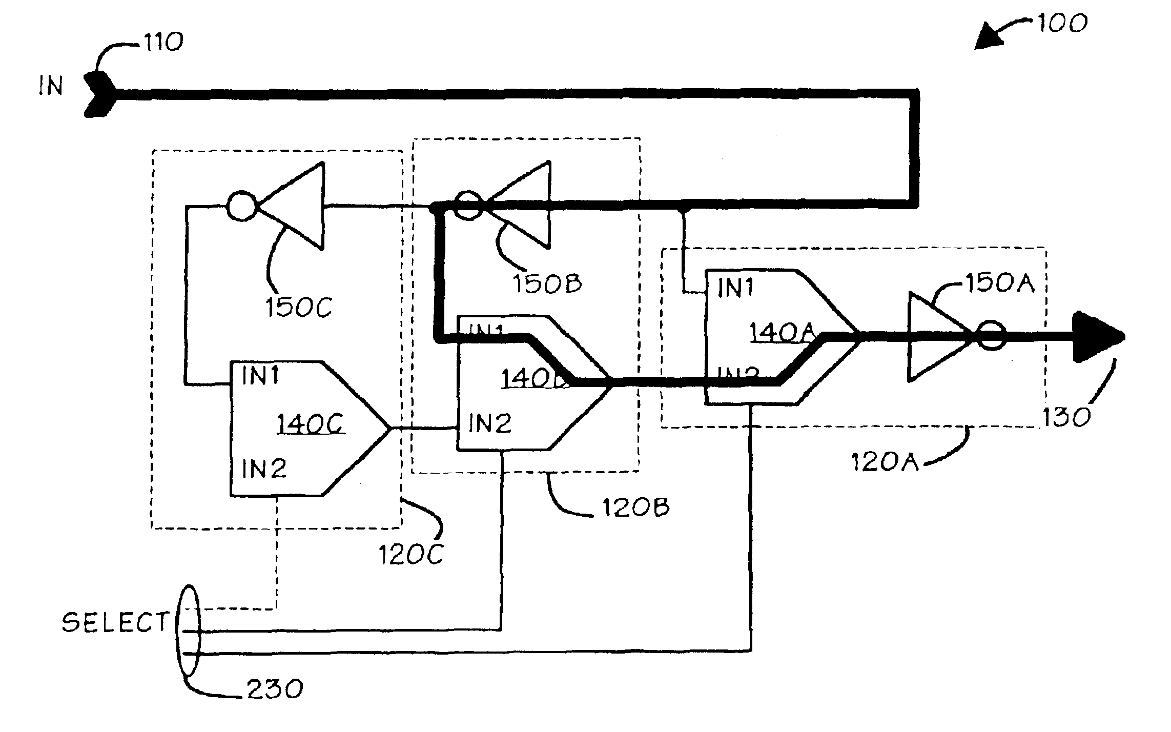
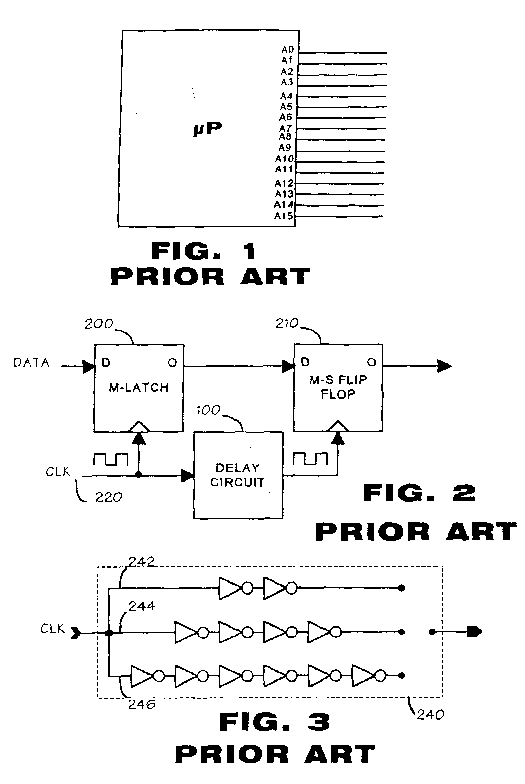
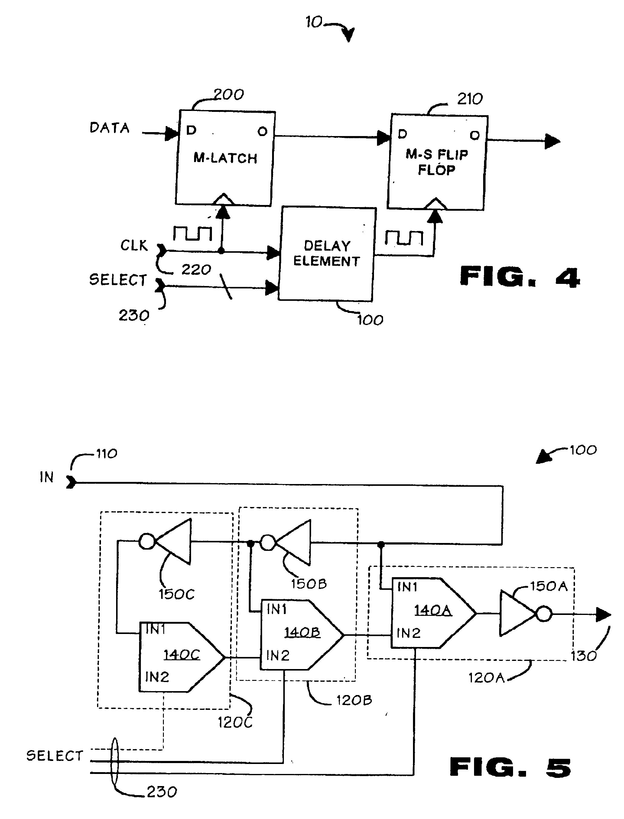
[0025]Turning to FIG. 4, there is shown a data circuit 10 according to an embodiment of the present invention. The data circuit 10 may be used in an integrated circuit, such as the microprocessor of FIG. 1, in place of the circuit of FIG. 2. The data circuit 10 provides a conventional latch 200 and master slave flip flop 210. A data signal generated from a source internal to the integrated circuit 10 (not shown) is input to the latch 200. A clock signal 220 is input directly to the latch 200. From the latch, the data is input to the master slave flip flop 210. The clock 220 propagates through a variable delay element 100 to the flip flop 210. The delay element 100 provides variable delay to the propagation of the clock signal 220 to the flip flop 210. The variable delay is adjusted according to the value of a multibit SELECT signal 230 input to the delay element 100.

[0026]FIG. 5 is a block diagram of an embodiment of the delay element 100. The delay element 100 accepts an input sign...


PUM


Abstract

A method and apparatus for delay tuning an integrated circuit which includes a delay element that includes a plurality of delay stages interconnected in a cascaded relationship, each stage imposing an incremental delay upon the input signal when enabled, the delay element receives a selection signal that determines how many of the delay stages are enabled. By varying the select signal, the delay element imposes, a variable delay upon the input signal for testing and evaluation.

Description

CROSS REFERENCE TO RELATED APPLICATIONS[0001]This application is a continuation of application Ser. No. 08 / 989,917, filed Dec. 12, 1997 now U.S. Pat. No. 6,628,157, the contents of which are incorporated herein by reference.BACKGROUND OF THE INVENTION[0002]1. Field of the Invention[0003]The present invention relates to a method and apparatus that facilitates delay tuning of integrated circuits and, in particular, to a method and apparatus for providing a software implementation of delay tuning in integrated circuits.[0004]2. Description of the Prior Art[0005]Timing analysis is a critical element of the design of an integrated circuit. Vendors of integrated circuits often standardize the performance of their circuits to ensure that they meet a standardized timing scheme. The scheme may be the subject of a market-wide standard or may be established by the vendor itself. Often, the vendors distribute timing diagrams with their products to permit purchasers to integrate the products int...

Claims


Application Information

Patent Timeline
Patent Type & Authority Patents(United States)
IPC IPC(8): H03H11/26H03K5/13H03K5/135H03K5/00
CPCH03H11/265H03K5/135H03K5/133H03K2005/00078H03K2005/00058
Inventor KUPPUSWAMY, RAVISHANKARTAYLOR, GREGORY
Owner INTEL CORP
Learn More