Gooseneck surgical retractor positioner and method of its use

a technology of surgical retractor and positioner, which is applied in the field of surgical equipment, can solve the problems of one side sometimes riding up and out of the wound, and achieve the effect of easy and quick movement into the position

Inactive Publication Date: 2005-05-03
BOSS INSTR
View PDF29 Cites 97 Cited by
  • Summary
  • Abstract
  • Description
  • Claims
  • Application Information

AI Technical Summary

Benefits of technology

[0011]Yet another need exists for a stabilizing apparatus which is easily and quickly moved into position and then locked into position securing a plurality of retractor blades at a specific spatial orientation.

Problems solved by technology

While two retractor blades may be placed within an incision in a patient with this device, a problem experienced by surgeons is that one side sometimes tends to ride up and out of the wound since the incision is under tension (i.e., tends to close itself).
While patents such as U.S. Pat. No. 6,234,961 are directed to retractor assemblies, this device is not a traditional retractor as the only way to retract tissue with this device without using other retractors or retractor blades is to loosen a clamp and pull the retractor blade along its shaft axis.
As a practical matter this would be very difficult is the blades are already under tension spreading an incision apart.

Method used


Image

  • Gooseneck surgical retractor positioner and method of its use
  • Gooseneck surgical retractor positioner and method of its use
  • Gooseneck surgical retractor positioner and method of its use

Examples


Embodiment Construction

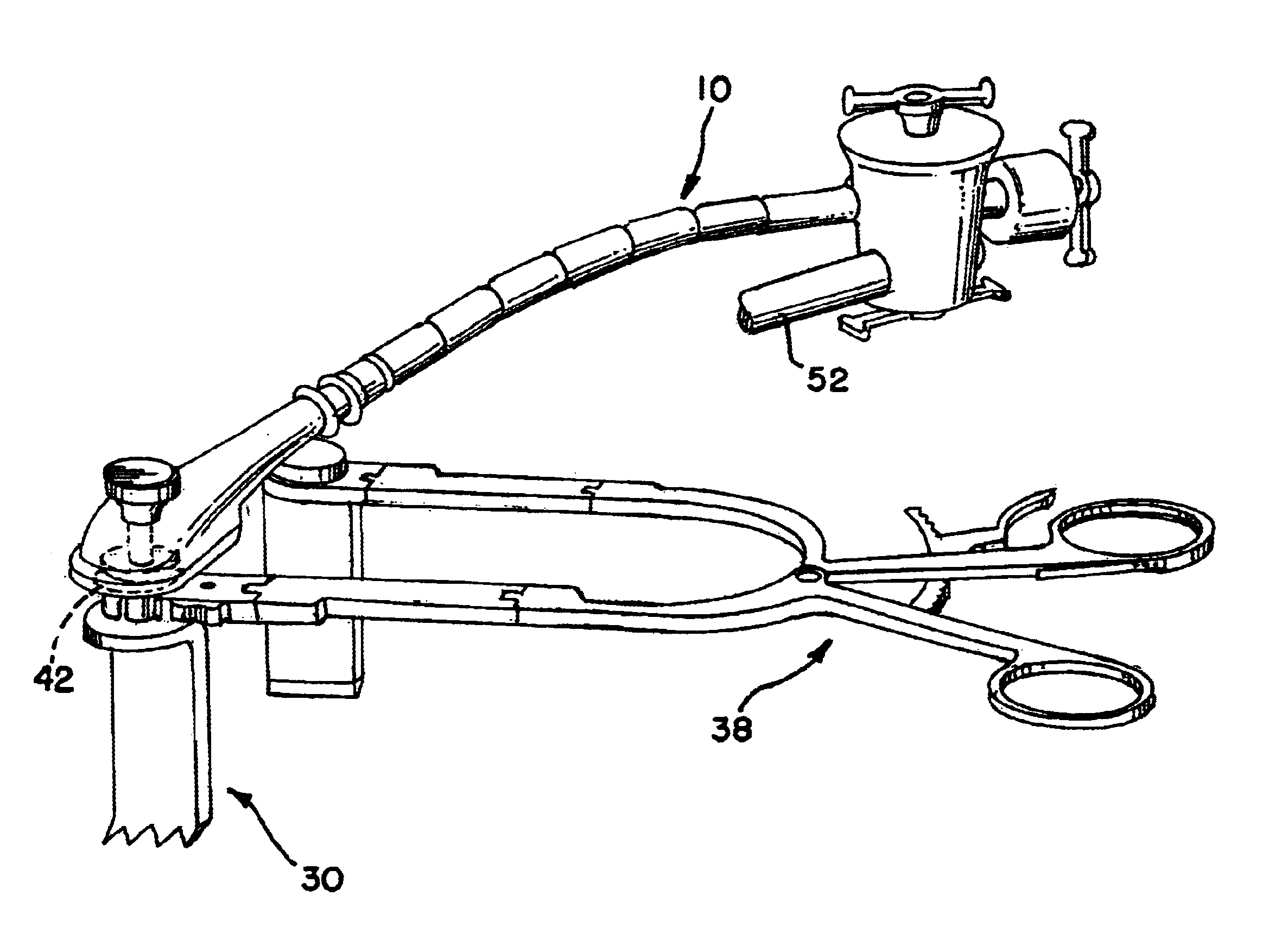
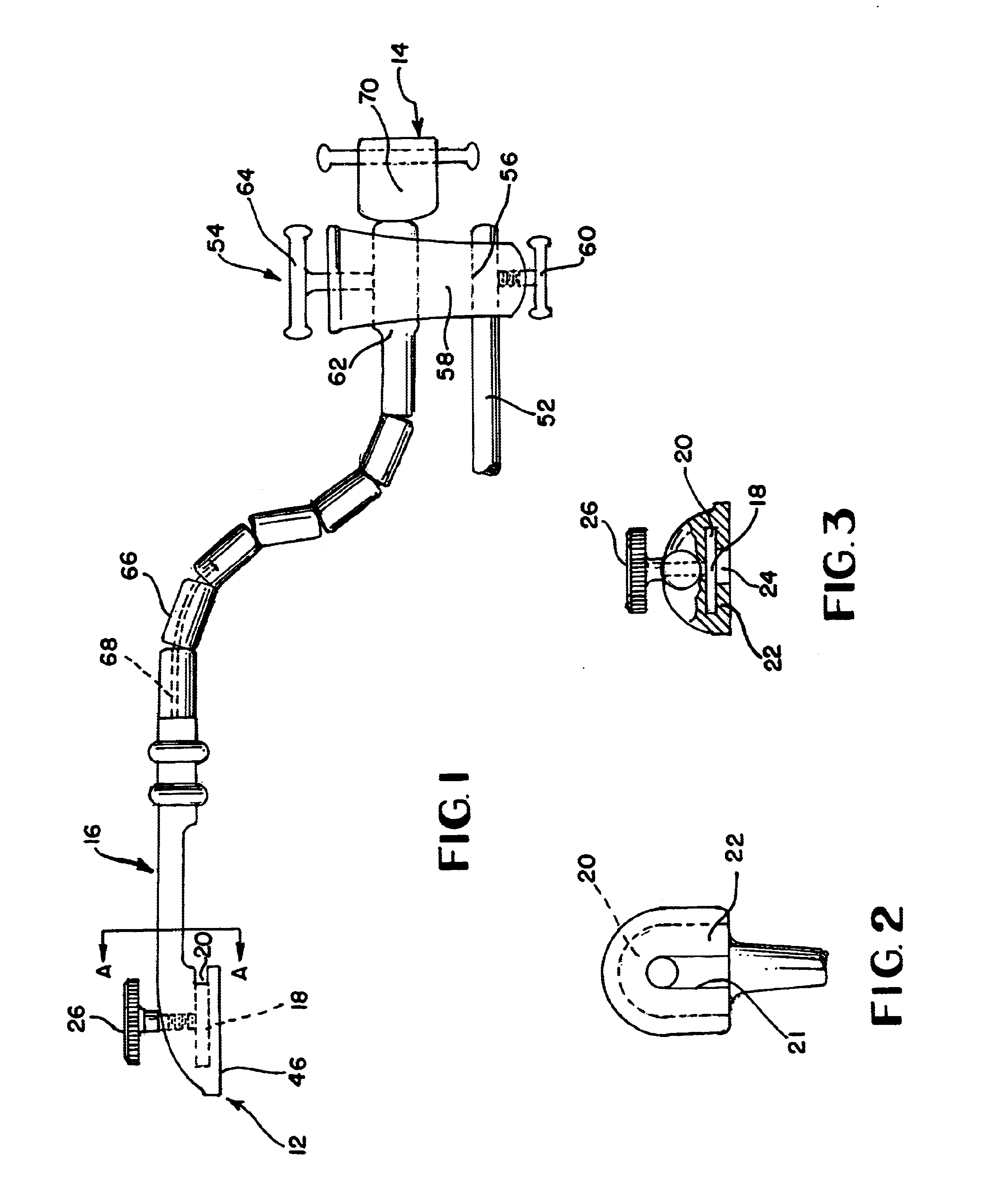
[0021]FIG. 1 illustrates a preferred embodiment of a positioner 10, illustrated as a gooseneck positioner, having a first end 12 and a second end 14. The first end 12 has a connector 16 with a socket 18. The socket 18 has a slot 20 above a ledge 22 about an opening 24. The opening allows for a post of a connection head to be inserted into the socket while receiving a cap into the slot 20. A retainer 26, a screw is illustrated, may positively lock the connection head to the first end of the positioner 10.

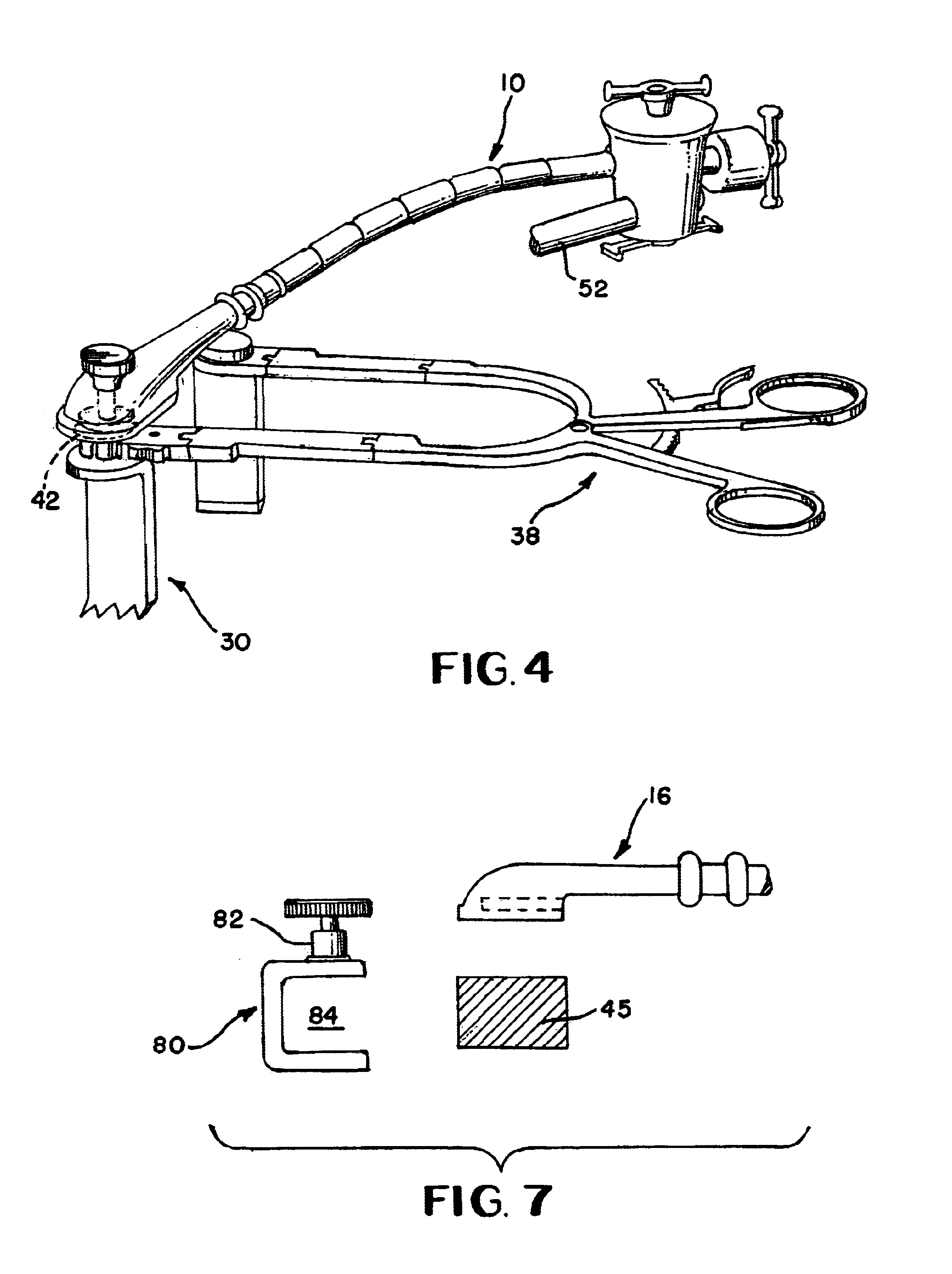
[0022]Reference to FIG. 6 is helpful to see the connection of the connector 16 with a connection head 28 on a retractor blade 30 as shown in FIG. 4. The connection head 28 has two loading portions 32,34 separated by cap 36. The first loading portion 32 may be utilized by the connector 16 of the positioner 10. Of course, if the connector 16 were designed in another manner, the second loading portion 34 could possibly be utilized with the connector 16 as shown in FIG. 4. Other connecti...


PUM


Abstract

A gooseneck positioner secures a fixed support to one of a surgical spreader retractor and a connection head on a retractor blade. The positioner prevents the two retractor blades from riding out of an incision during a surgical operation. The gooseneck mechanism allows for the relative easy placement and then securing of the positioner at a desired location.

Description

[0001]This application claims the benefit of U.S. Provisional Patent Application No. 60 / 327,437 filed Oct. 5, 2001, and U.S. patent application Ser. No. 10 / 117,929 filed Apr. 5, 2002, now U.S. Pat. No. 6,733,444.FIELD OF THE INVENTION[0002]The present invention relates generally to a surgical apparatus and its method of use with retractor blades and retractor blade holders to assist in retaining retractor blades at a specific location, and more particularly to prevent retractor blades from riding up out of an incision once positioned by a surgeon.BACKGROUND OF THE INVENTION[0003]When conducting some surgical procedures, it is often desirable to retract tissue. U.S. Pat. No. 6,042,540 shows several retractor designs which allow for top loading or side loading of retractor blades into a socket. The side loading feature of this, and other prior art, is believed to be advantageous whereby the surgeon's vision is not obscured while connecting, or disconnecting a blade from a retractor. T...

Claims


Application Information

Patent Timeline
Patent Type & Authority Patents(United States)
IPC IPC(8): A61B17/02A61B17/28A61B1/32A61B17/00
CPCA61B17/02A61B17/0206A61B1/32A61B2017/2837A61B2017/0046A61B2017/00464A61B17/2812
Inventor PHILLIPS, BURNS P.GRIFFITH, LARRY
Owner BOSS INSTR
Why Eureka
Try Eureka