Temporary Cap for a Blownout Subsea Wellhead

a technology for subsea wells and caps, which is applied in underwater drilling, drilling machines and methods, and well accessories. it can solve the problems of difficult to deal with blowouts in very deep water, less effective, and marine pollution, and achieve the effect of easy and quick movement into position

Inactive Publication Date: 2014-04-03
REEVES CHARLES
View PDF5 Cites 2 Cited by
  • Summary
  • Abstract
  • Description
  • Claims
  • Application Information

AI Technical Summary

Benefits of technology

[0011]The present invention provides a device and a means for containing the flow of oil from a subsea oil well blowout. The device is easily and quickly moved into position to contain the oil from a subsea well blowout. The device provides an improved method for recovering the oil flowing from a subsea well blowout and preventing the mixing of such fluids with large quantities of the seawater. An improved method of oil containment includes the positioning of a vertical capsule over a subsea well blowout and the conducting of oil through a conduit to surface processing and storage equipment. In addition, an improved method includes the formation of a seal completely around the blownout wellhead.

Problems solved by technology

It is very difficult to deal with a blowout in very deep water because of the remoteness and limited experience with this type of situation.
However, even if there is a surface fire, most of the oil remains unburned and causes marine pollution.
While many of the techniques used in on shore operations to fight blowouts can also be applied in the offshore environment, they often prove to be less effective and require a much longer time period for implementation.
Thus, for example, while relief wells can be drilled to intercept the blowout well, a great amount of time may be required in the drilling operation.
Due to the rugged offshore environment, more time is required to drill the relief wells than would be required in an onshore operation.
As a result of all of these difficulties, many months can pass between the occurrence of an offshore oil well blowout and the successful final capping of the blown out well.
In the intervening time, large quantities of oil and gas can escape into the ocean with serious environmental impact.
The dome structures are generally not suitable for containment of wellhead blowouts where large quantities of gas and oil are erupting.
The force of such blowouts would tend to lift most domes.
The dome shape is also not effective in diverting high speed flow.
These structures are not effective because the wellhead is not completely sealed thereby allowing oil to pollute the surrounding sea water.

Method used


Image

  • Temporary Cap for a Blownout Subsea Wellhead
  • Temporary Cap for a Blownout Subsea Wellhead
  • Temporary Cap for a Blownout Subsea Wellhead

Examples


Embodiment Construction

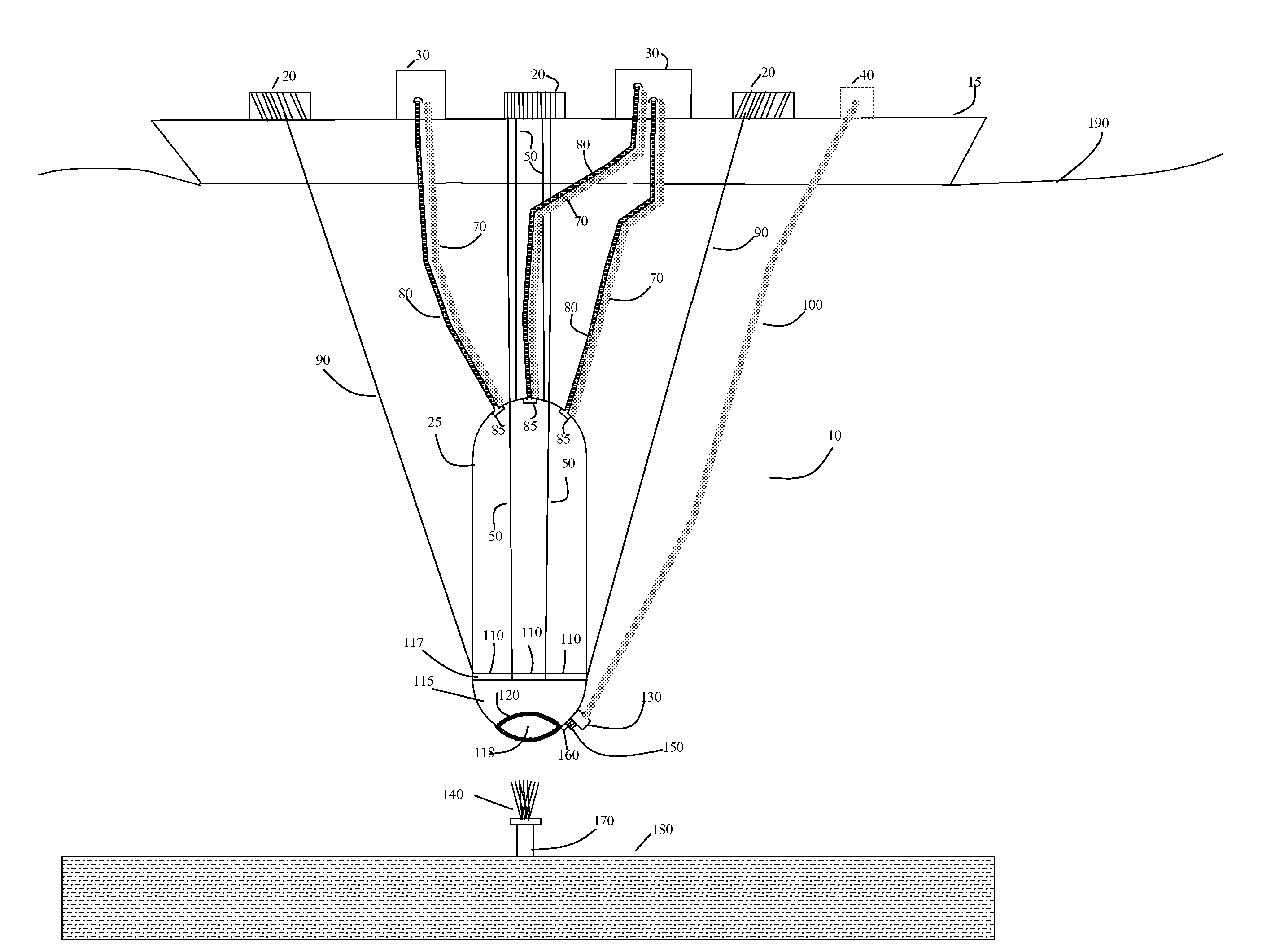
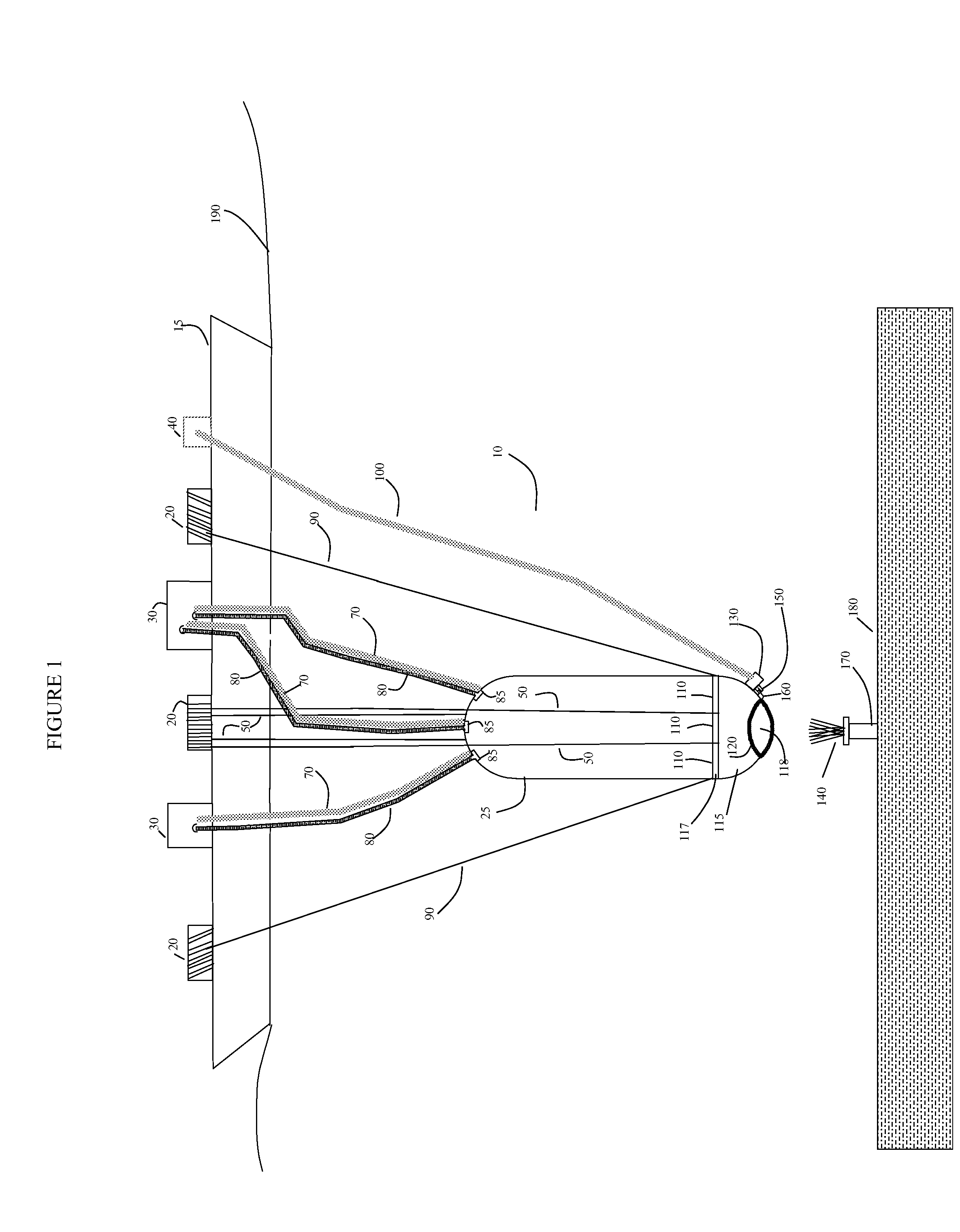
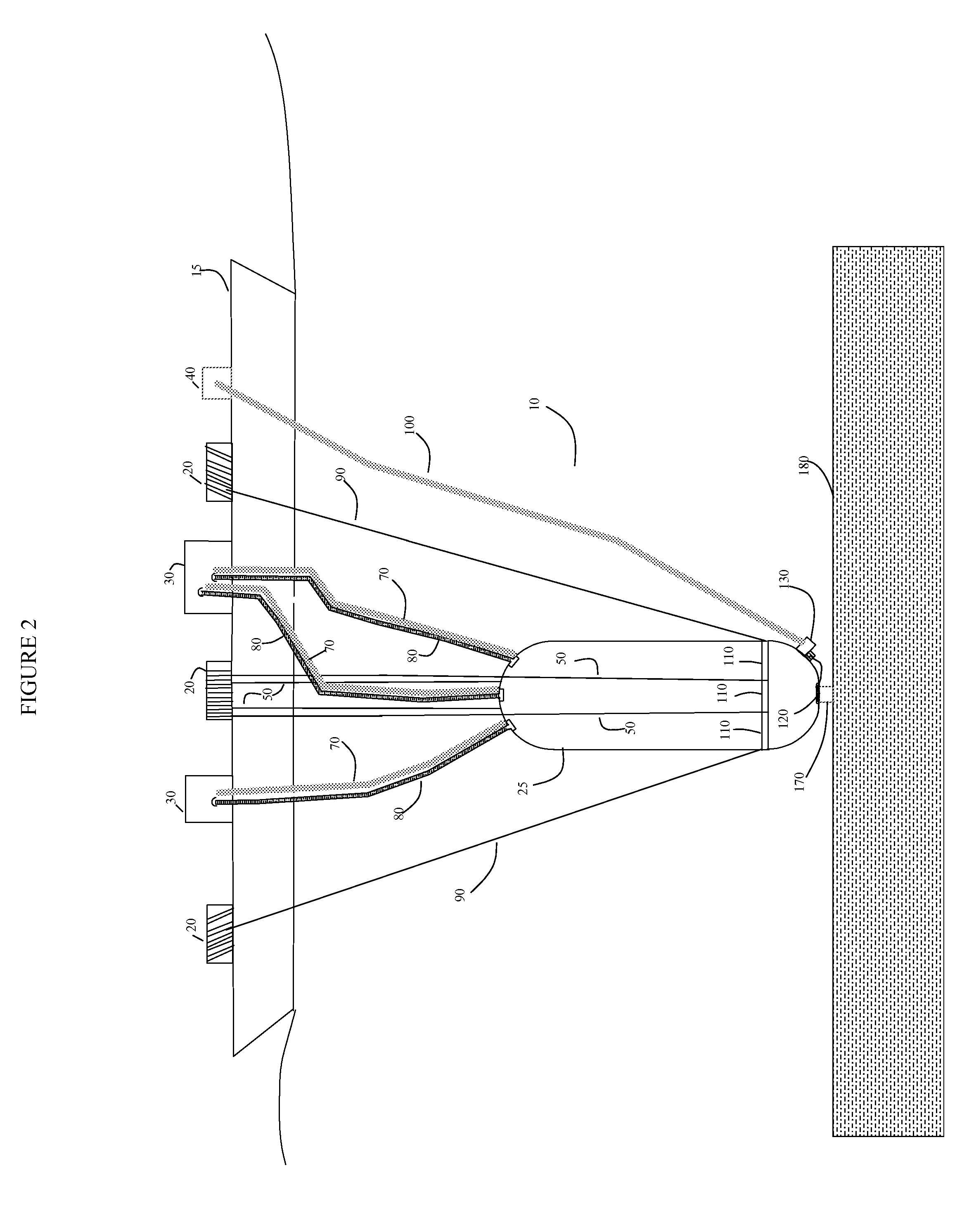
[0017]The present invention will now be described more fully hereinafter, in which preferred embodiments of the invention are shown. The temporary cap for a blownout subsea wellhead that forms the basis of the present invention is designated generally by the reference number 10. This invention may, however, be embodied in different forms and should not be construed as limited to the embodiments set forth herein. Rather, these embodiments are provided so that this disclosure will be thorough and complete, and will fully convey the scope of the invention to those skilled in the art. In the drawings, like numbers refer to like elements throughout. The scaling of some components on the drawings may be exaggerated for clarity.

[0018]With reference now to FIGS. 1, 2, 3, and 4 the device 10 according to the present invention and its placement over a blown out subsea wellhead is illustrated. In FIG. 1, a subsea wellhead 170 is illustrated erupting a flow of oil forming a flume 140. A barge 1...


PUM


Abstract

A device for collecting and confining oil escaping from a sea bottom wellhead blowout. The device is easily and quickly moved into position to contain the oil from a subsea well blowout. The device provides an improved method for recovering the oil flowing from a subsea well blowout and preventing the mixing of such fluids with large quantities of the seawater. An improved method of oil containment includes the positioning of a vertical capsule over a subsea well blowout and the conducting of oil through a conduit to surface processing and storage equipment. In addition, an improved method includes the formation of a seal completely around the blownout wellhead.

Description

CROSS-REFERENCE TO RELATED APPLICATIONS [0001]This application claims the benefit of priority to U.S. Provisional Patent Application No. 61 / 709,132 filed on Oct. 2, 2012 by the present inventor, the contents of which are incorporated herein by reference.STATEMENT REGARDING FEDERALLY SPONSORED RESEARCH OR DEVELOPMENT [0002]Not ApplicableREFERENCE TO SEQUENCE LISTING, A TABLE, OR A COMPUTER PROGRAM LISTING COMPACT DISK APPENDIX [0003]Not ApplicableBACKGROUND OF THE INVENTION [0004]1. Field of the Invention[0005]The present invention relates to a device and a means for collecting and confining oil escaping from a sea bottom wellhead blowout.[0006]2. Background of the Invention[0007]Subsea wells have the wellhead and pressure control equipment located on the seabed. Typically subsea wells may vary from depths of 10 feet to 8,000 feet. It is very difficult to deal with a blowout in very deep water because of the remoteness and limited experience with this type of situation. The Deepwater...

Claims


Application Information

Patent Timeline
Patent Type & Authority Applications(United States)
IPC IPC(8): E21B43/01
CPCE21B43/0122
Inventor REEVES, CHARLES
Owner REEVES CHARLES
Why Eureka
Try Eureka