
Piston for an internal combustion engine

a technology for internal combustion engines and pistons, which is applied to engines, mechanical equipment, machines/engines, etc., can solve the problems of too much air to be mixed with oil, the oil level in the oil duct in the piston becomes too small, and the structure demonstrates the defect of achieving a continuous oil fill level of the cooling duct, so as to improve the cooling efficiency and control the oil flow

Inactive Publication Date: 2011-11-03
VOLVO LASTVAGNAR AB
View PDF4 Cites 8 Cited by
  • Summary
  • Abstract
  • Description
  • Claims
  • Application Information

AI Technical Summary

Benefits of technology

[0007]An advantage of this aspect is that the oil flow can be better controlled resulting in improved cooling efficiency.
[0008]Another advantage is that oil may be forced from the oil inlet to the oil outlet in almost a complete rotation of a crank axle in said internal combustion engine.
[0014]An advantage of this embodiment is that the oil level can be better controlled.
[0016]An advantage of this embodiment is that the oil circulation can be better controlled.

Problems solved by technology

These structures demonstrates defects in achieving a continuous oil fill level of the cooling duct, due to disadvanatageous flow and friction conditions during entry of the cooling oil into the inlet.
However, in U.S. Pat. No.7,051,684 there is still a problem with the fill level in the oil cooling duct and the amount of oil circulating in said oil cooling duct in said piston for achieve sufficient cooling of the piston.
Especially, there is a problem if the oil level in the oil duct in said piston becomes to small.
The small oil level may cause too much air to be mixed with the oil when the engine rev is in a higher range.
Air is a very bad thermal conductor, which decreases the cooling efficiency dramatically.
Another problem with the design of U.S. Pat. No. 7,051,684 is that the circulation of oil in the oil cooling duct is too low.
A too low circulation of oil in the oil cooling duct will further decrease the cooling efficiency.

Method used


Image

  • Piston for an internal combustion engine
  • Piston for an internal combustion engine

Examples


Embodiment Construction

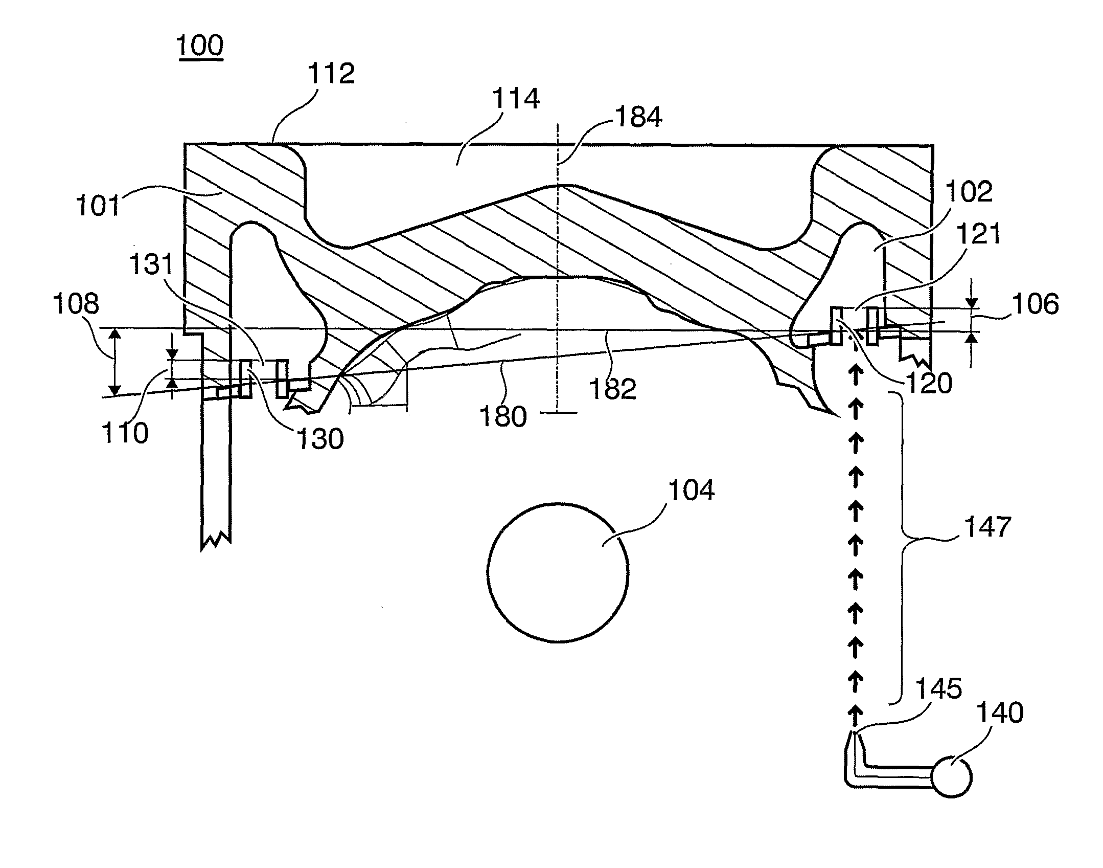
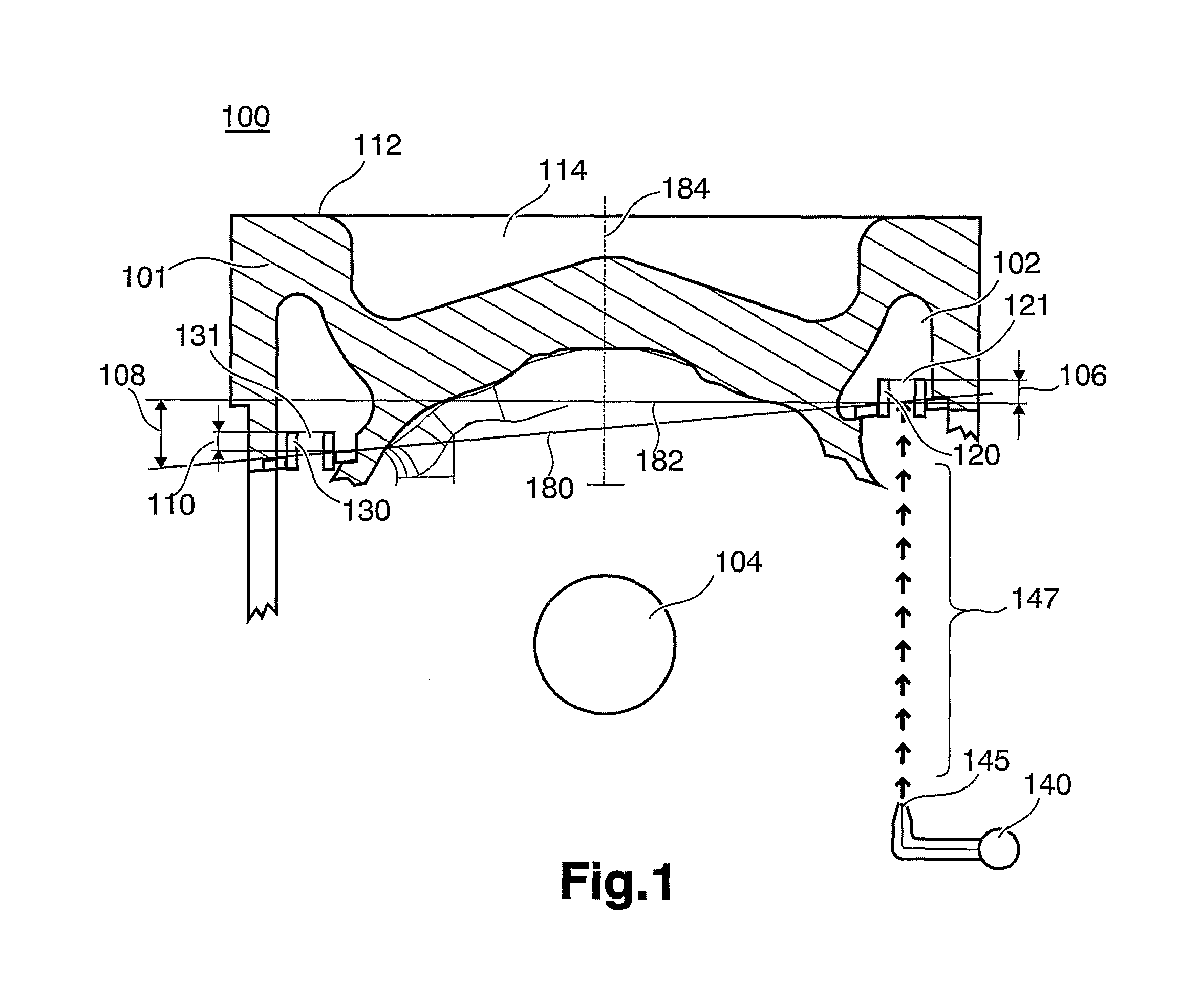
[0020]FIG. 1 depicts schematically a cross sectional view of an example embodiment according to the present invention of a cooling structure for an internal combustion engine piston 100. Said piston 100 comprising a body 101, a top surface 112, a combustion chamber cavity 114, an oil cooling channel 102, a wrist pin opening 104, an oil inlet 121, an oil inlet mechanical stop 120, an oil outlet 131, and an oil outlet mechanical stop 130.

[0021]Oil is provided to the oil cooling channel 102 in said piston by a nozzle 145 attached to an oil pump 140. The oil is injected into the oil inlet 121 in the piston from below as indicated by arrows 147 in FIG. 1. The oil pump 140 may be the same pump as used to circulate oil to the engine bearings. A separate pump 140 may also be used for injecting oil to the pistons.

[0022]The combustion chamber cavity is typical for self igniting engines such as diesel engines. However, a top portion in natural aspirated gasoline engines may very well have the ...


PUM


Abstract

A cooling structure for an internal combustion engine piston is provided. The piston includes an oil cooling channel integrated in the piston. The oil cooling channel has a bottom surface facing towards a top surface of the piston and a top surface facing away from the top surface of the piston. The oil cooling channel is provided with an oil inlet and an oil outlet which are laterally separated from each other. The bottom surface and / or the top surface of the oil cooling channel is slanted relative to a central axis of a wrist pin opening provided in said piston.

Description

BACKGROUND AND SUMMARY[0001]The present invention relates to a cooling structure for an internal combustion engine piston.[0002]Cooled pistons having an oil inlet are known from example U.S. Pat. No. 3,221,718 and DE 3733964. The oil inlets used as catch funnels for cooling oil that is dispensed from an oil spraying nozzle connected with the engine housing have inners walls that are configured to be funnel shaped, cylindrical, oval or in the form of a venture jet. In order to achieve better distribution, in the cooling duct, of the oil captured in this manner, additional dividers are inserted into the wall of the cooling duct, which lie opposite the exit surface of the oil inlet.[0003]Using such shaping structures, the result supposed to be achieved is that the oil stream that widens from the oil spraying nozzle is captured and passed to the cooling duct. These structures demonstrates defects in achieving a continuous oil fill level of the cooling duct, due to disadvanatageous flow ...

Claims


Application Information

Patent Timeline
Patent Type & Authority Applications(United States)
IPC IPC(8): F01P1/04
CPCF01P3/10F16J1/09F02F3/22
Inventor ASK, KENNETHHANSSON, ANDERSLUNDIN, LARS
Owner VOLVO LASTVAGNAR AB
Learn More