
Camshaft phaser

a camshaft and phaser technology, applied in the direction of valve arrangements, machines/engines, mechanical equipment, etc., can solve the problems of adding load to the internal combustion engine, adding cost and complexity to the system, and adding single check valves, etc., to increase the phasing rate, simple and economical implementation, and increase the oil flow

Active Publication Date: 2017-05-11
DELPHI TECH IP LTD
View PDF3 Cites 9 Cited by
  • Summary
  • Abstract
  • Description
  • Claims
  • Application Information

AI Technical Summary

Benefits of technology

The patent describes a device called a camshaft phaser that can change the timing of a camshaft in an engine. It uses an input member that connects to the crankshaft, an output member that connects to the camshaft, and a valve spool that can move between two positions. The valve spool has two passages that allow oil to flow in either direction, which can change the timing of the camshaft. This device can make it easier to control the timing of the engine and improve its performance.

Problems solved by technology

While the camshaft phaser of Lichti et al. may be effective, the camshaft phaser may be parasitic on the lubrication system of the internal combustion engine which also supplies the oil for rotating the rotor relative to the stator, thereby requiring increased capacity of an oil pump of the internal combustion engine which adds load to the internal combustion engine.
However, requiring two check valves adds cost and complexity to the system.
rs. While Simpson et al. eliminates one check valve compared to Smith et al., the passages of Simpson et al. that are required to implement the single check valve add further complexity because the check valve is located remotely from the valve
However, placement of the check valve within the valve spool as implemented by Wigsten complicates the manufacture of the valve spool and adds further complexity to passages needed in the valve body within which the valve spool is slidably disposed.

Method used


Image

  • Camshaft phaser
  • Camshaft phaser
  • Camshaft phaser

Examples


Embodiment Construction

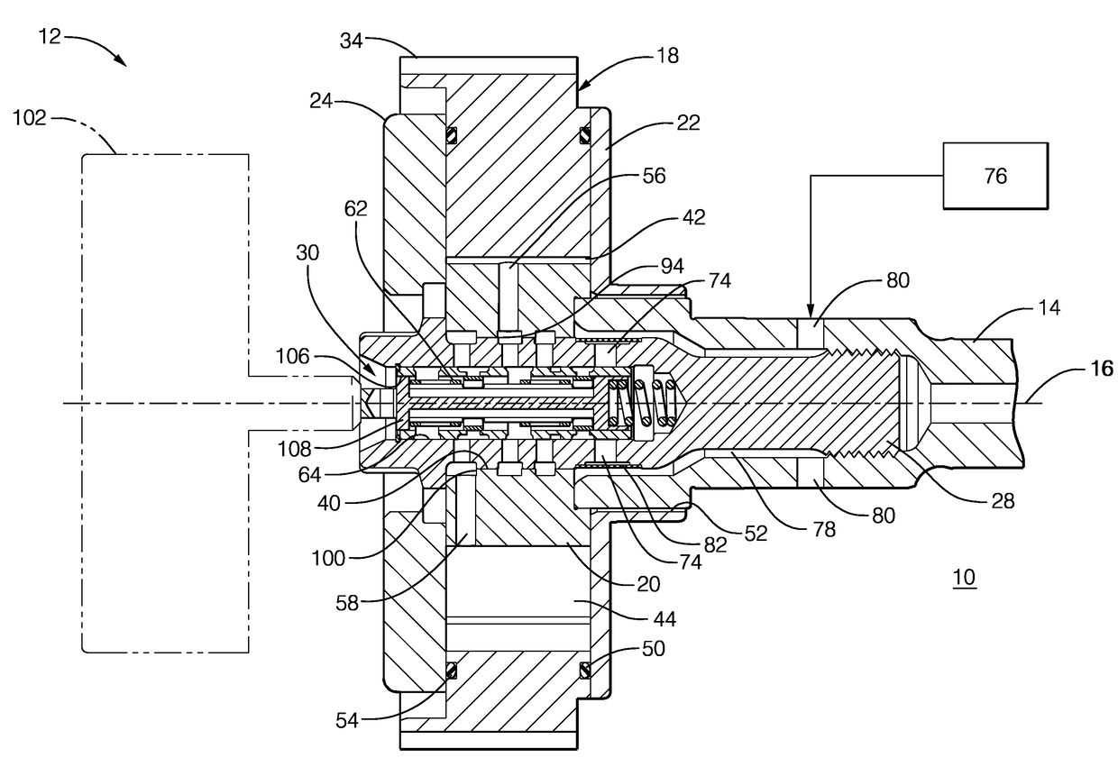
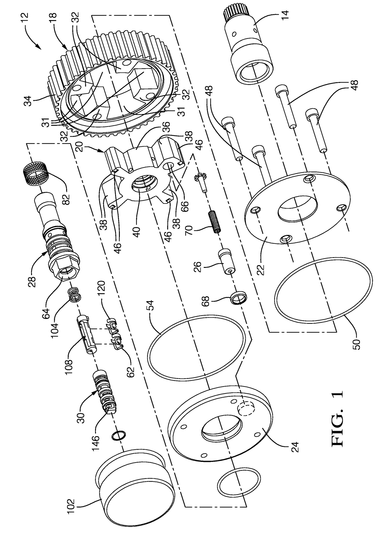
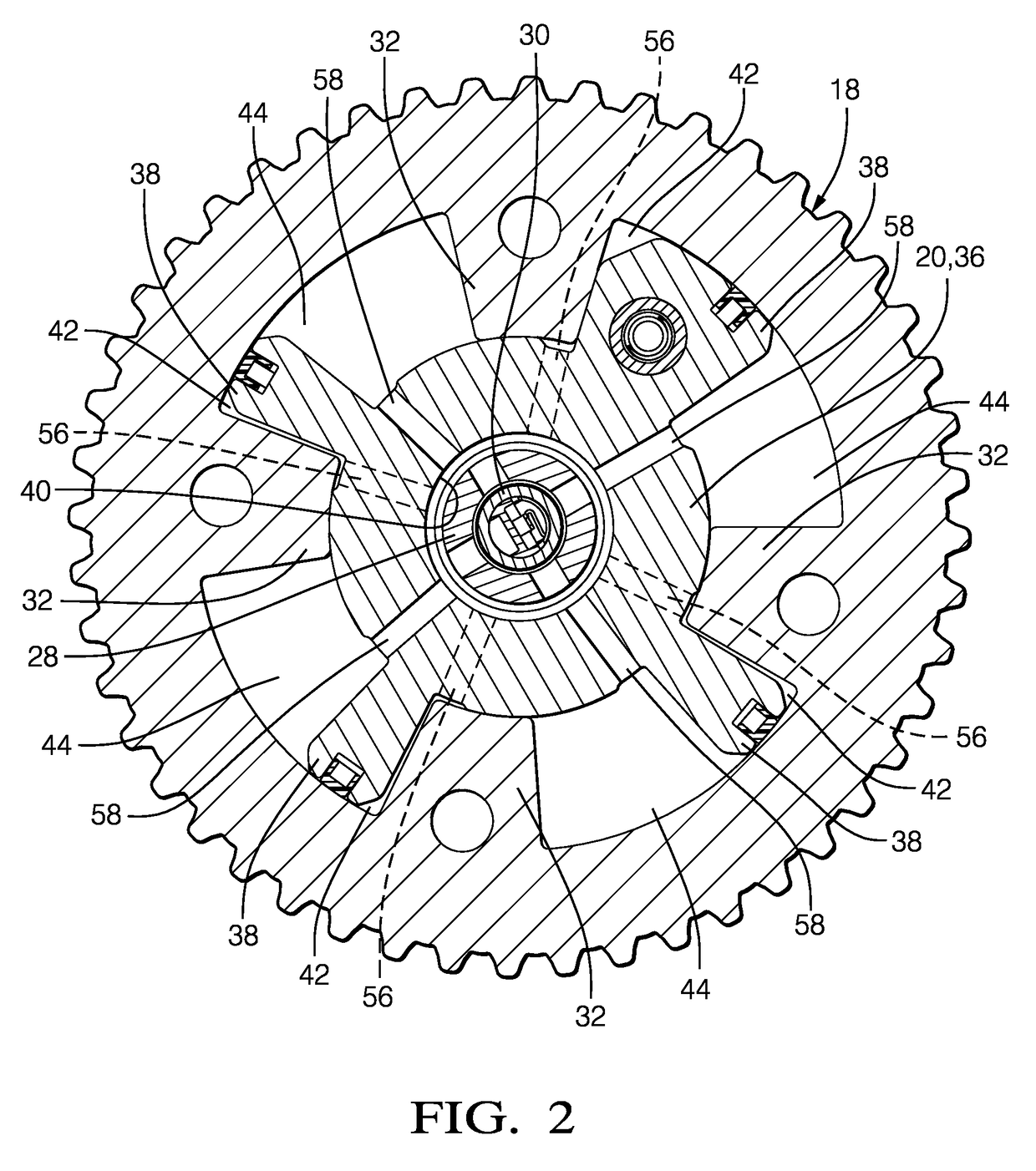
[0025]In accordance with a preferred embodiment of this invention and referring to FIGS. 1-4, an internal combustion engine 10 is shown which includes a camshaft phaser 12. Internal combustion engine 10 also includes a camshaft 14 which is rotatable about a camshaft axis 16 based on rotational input from a crankshaft and belt (not shown) driven by a plurality of reciprocating pistons (also not shown). As camshaft 14 is rotated, it imparts valve lifting and closing motion to intake and / or exhaust valves (not shown) as is well known in the internal combustion engine art. Camshaft phaser 12 allows the timing between the crankshaft and camshaft 14 to be varied. In this way, opening and closing of the intake and / or exhaust valves can be advanced or retarded in order to achieve desired engine performance.

[0026]Camshaft phaser 12 generally includes a stator 18 which acts and an input member, a rotor 20 disposed coaxially within stator 18 which acts as an output member, a back cover 22 clos...


PUM


Abstract

A camshaft phaser includes an input member and an output member defining an advance chamber and a retard chamber; a valve spool moveable along an axis between an advance position and a retard position and having a valve spool bore with a phasing volume and a venting volume defined therein such that the phasing volume is fluidly segregated from the venting volume, the valve spool having a first spool recirculation passage and a second spool recirculation passage which is diametrically opposed to the first spool recirculation passage. The first spool recirculation passage and the second spool recirculation passage provide paths for oil to flow from the advance chamber or the retard chamber to the phasing volume depending on the position of the valve spool.

Description

TECHNICAL FIELD OF INVENTION[0001]The present invention relates to a camshaft phaser for varying the phase relationship between a crankshaft and a camshaft in an internal combustion engine; more particularly to such a camshaft phaser which is a vane-type camshaft phaser; even more particularly to a vane-type camshaft phaser which uses torque reversals of the camshaft to actuate the camshaft phaser.BACKGROUND OF INVENTION[0002]A typical vane-type camshaft phaser for changing the phase relationship between a crankshaft and a camshaft of an internal combustion engine generally comprises a plurality of outwardly-extending vanes on a rotor interspersed with a plurality of inwardly-extending lobes on a stator, forming alternating advance and retard chambers between the vanes and lobes. Engine oil is selectively supplied to one of the advance and retard chambers and vacated from the other of the advance and retard chambers by a phasing oil control valve in order to rotate the rotor within ...

Claims


Application Information

Patent Timeline
Patent Type & Authority Applications(United States)
IPC IPC(8): F01L1/344F01L1/047
CPCF01L1/3442F01L2001/34426F01L1/047F01L1/34409F01L2001/34453F01L2001/34456F01L2001/34433F01L1/34
Inventor HALTINER, JR., KARL J.
Owner DELPHI TECH IP LTD
Learn More