Gas flow monitoring device

a technology of gas flow and monitoring device, which is applied in the direction of check valves, valve details, valve types, etc., can solve the problems of increasing manufacturing and warehousing costs, unable to specify the specific set-up right on the site of installation as might be desired by the responsible installation firm, and unable to adjust the pre-defined reseat flow

Inactive Publication Date: 2005-05-17
MERTIK MAXITROL
View PDF11 Cites 45 Cited by
  • Summary
  • Abstract
  • Description
  • Claims
  • Application Information

AI Technical Summary

Benefits of technology

[0013]Further advantageous arrangements of the invention are described in the other patent claims. For example, it has proved especially favourable if the spacer block is equipped with a lock-in grid by which the spacer block can catch and take hold behind the collars provided at the inlet guide and in this way secure the spacer block in its position against the force of a spring that rests with its one side at the inlet guide opposite to the reseat body and with its other side on the spacer block itself.
[0015]In this connection it has proved especially favourable that unintentional resetting of the pre-set value is avoided as the spacer block is provided with a locking piston which, however, is disabled in case the spacer block is moved against the force of the spring in order to intentionally alter the pre-set value.
[0016]There is another favourable arrangement in which the spacer block is always held within the inlet guide as the spacer block is provided with resilient lips assigned to each of the inlet guide's collars and in this way enable said collars to trip, whereat the tappets that also are specifically assigned to each of the inlet guide's collars prevent their pushing out.

Problems solved by technology

The disadvantage of all those solutions is that a pre-defined reseat flow can only be adjusted by using dedicated setting and testing equipment and, hence, such work is done preferably by the manufacturer at the time of producing said safety shut-off devices.
So, a specific set-up right on the site of installation as might be desired by the responsible installation firm is virtually impossible.
This, in turn, results in increased manufacturing and warehousing costs.

Method used


Image

  • Gas flow monitoring device
  • Gas flow monitoring device
  • Gas flow monitoring device

Examples


Embodiment Construction

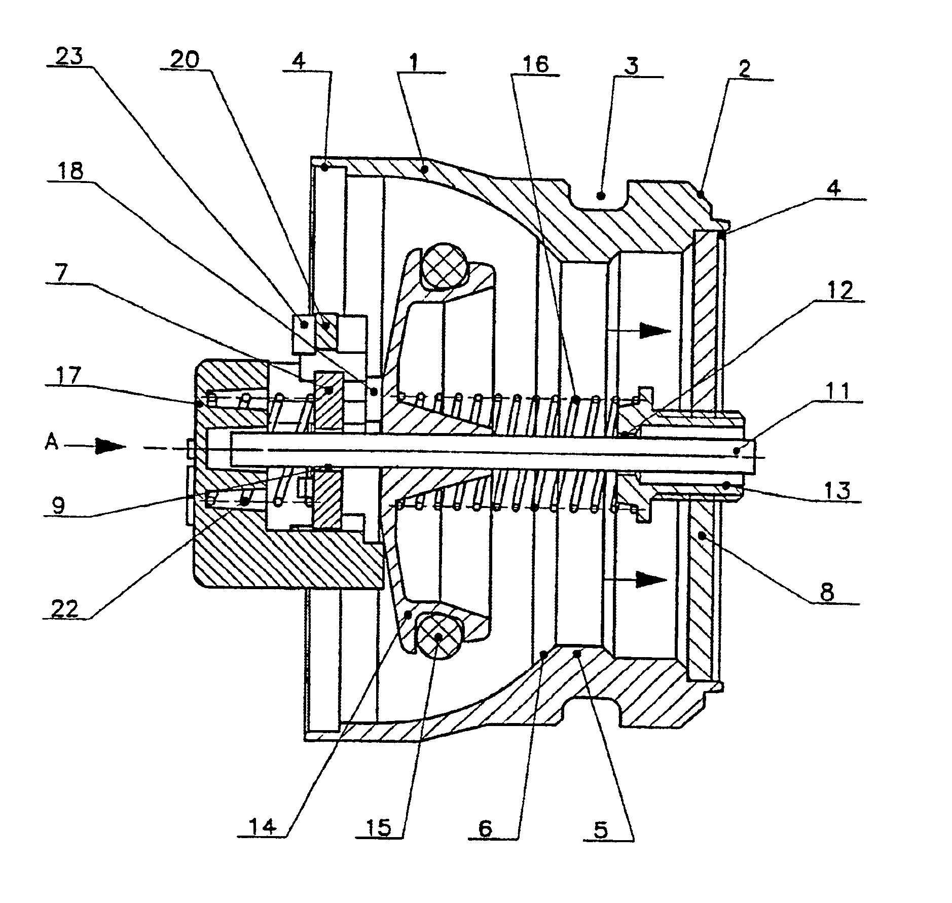
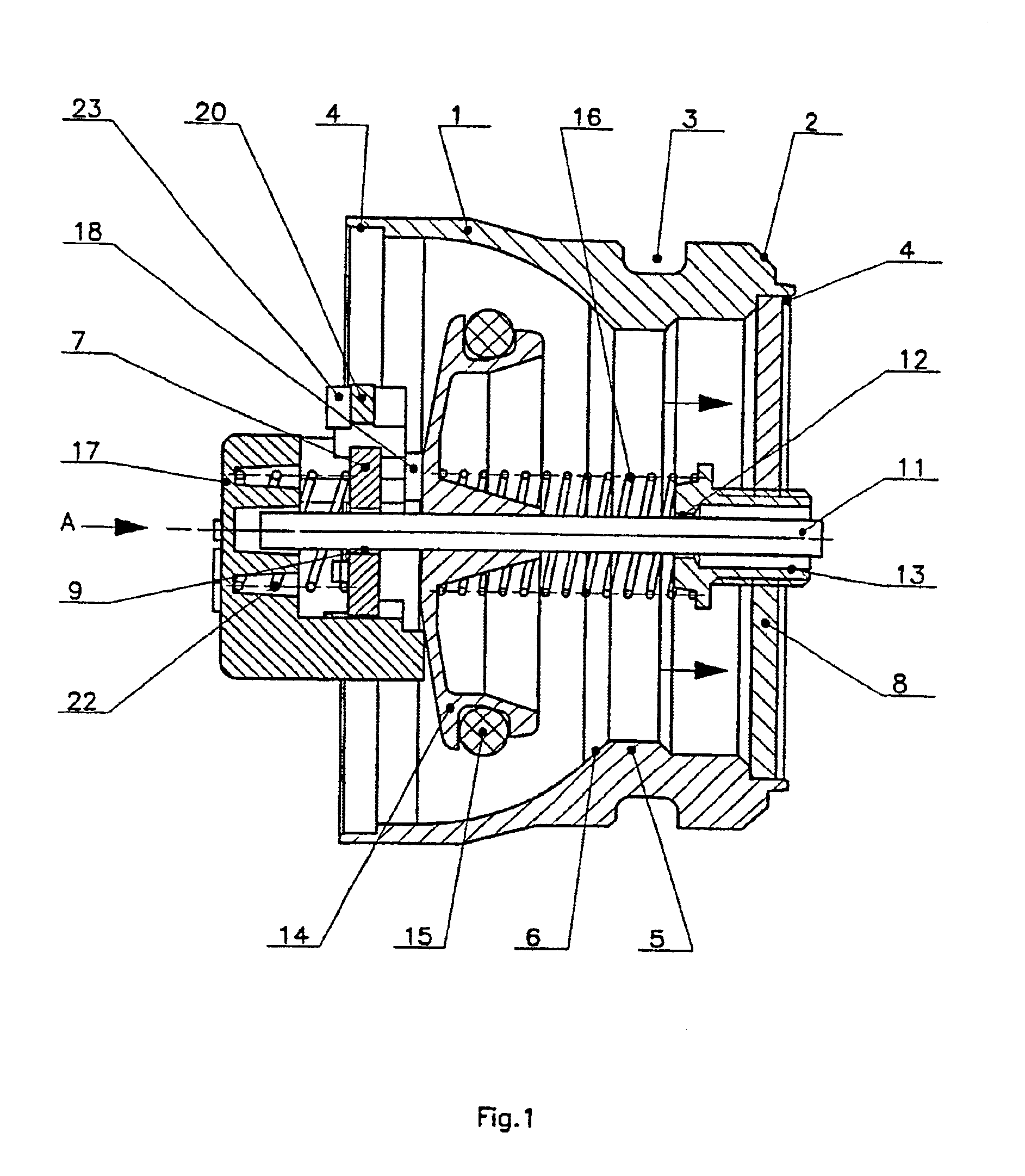
[0011]The invention is focusing on the issue of developing a gas flow monitoring device of the described type in which the adjustment / alteration of the reseat flow can also be made without the need of changes to its design, such as use of different springs depending on the desired reseat flow value, that is to say even after its manufacture. In particular, it should be possible to adjust the reseat flow after the valve has left the production facility, preferably at the time of its installation on site. According to the present invention the problem is solved by arranging a spacer block at the inlet mechanism which acts as a limit stop for the reseat body with the gas flow monitoring device in open position.

[0012]Thus, a solution has been found that removes the disadvantages of the prior art according to which adjustment of a pre-defined reseat flow—taking into account the time and money required to do so—was preferably done by the manufacturers of such safety shut-off devices at th...


PUM


Abstract

There is to be created a gas flow monitoring device in which the adjustment / alteration of the reseat flow can also be made without the need of changes to its design, that is to say even after its manufacture. In particular, it should be possible to adjust the reseat flow at the time of its installation on site. To this end, the gas flow monitoring device consists of a gas-tight casing (1) with a valve seat (6) in its interior for a reseat body (14) that can freely move inside the casing (1). Said reseat body (14) is fastened to a pin (11) that is supported by bearings located in both the inlet guide (7) and the outlet guide (8). Said reseat body (14) is kept in open position by a reseat spring (16) that rests with its one end on the outlet guide (8) and with its other end on the reseat body (14) itself. At the inlet guide (7) there is arranged a spacer block (17) that acts as a stop point (18) for the reseat body (14) with the gas flow monitoring device in open position.

Description

CROSS REFERENCE TO RELATED APPLICATIONS[0001]The disclosures in German Application No. 100 43 811.3, filed 6 Sep. 2000, and International Application No. PCT / EP01 / 10208, filed 5 Sep. 2001 are hereby incorporated by reference.TECHNICAL FIELD[0002]The invention relates to a gas flow monitoring device that automatically shuts off gas pipes in the event of an inadmissible flow increase.PRIOR ART[0003]Gas flow monitoring devices of that kind, employed in pipelines, e.g. upstream of gas valves, gas appliances, etc., are available in a large variety of designs. Their purpose is to discontinue gas supply if gas consumption exceeds a predefined value.[0004]WO 92 / 01184, for instance, describes a gas flow monitoring device of the above-mentioned type which in case of damage shuts a pipe system but does not effect a premature shutting off of the supply line if a consumer requires the gas volume corresponding to its rated output over a longer period. One valve in this safety shut-off device is d...

Claims


Application Information

Patent Timeline
Patent Type & Authority Patents(United States)
IPC IPC(8): F16K31/56F16K31/44F16K17/20F16K17/30
CPCF16K31/56F16K17/30Y10T137/7727Y10T137/7869
Inventor SCHULZE, KLAUS
Owner MERTIK MAXITROL
Why Eureka
Try Eureka