Communication network having a plurality of bridging nodes which transmit a beacon to terminal nodes in power saving state that it has messages awaiting delivery

a communication network and plurality of bridge nodes technology, applied in the field of radio data communication system, can solve the problems of difficult to maintain the integrity of such multi-hop rf data communication system, and achieve the effect of efficient and dynamic data handling

Inactive Publication Date: 2005-05-17
AVAGO TECH WIRELESS IP SINGAPORE PTE
View PDF46 Cites 22 Cited by
  • Summary
  • Abstract
  • Description
  • Claims
  • Application Information

AI Technical Summary

Benefits of technology

[0009]The present invention solves many of the problems inherent in a multiple-hop data communication system. The present invention comprises an RF Local-Area Network capable of efficient and dynamic handling of data by routing communications between the RF Terminals and the host computer through a network of intermediate base stations.
[0010]In one embodiment of the present invention, the RF data communication system contains one or more host computers and multiple gateways, bridges, and RF terminals. Gateways are used to pass messages to and from a host computer and the RF Network. A host port is used to provide a link between the gateway and the host computer. In addition, gateways may include bridging functions and may pass information from one RF terminal to another. Bridges are intermediate relay nodes which repeat data messages. Bridges can repeat data to and from bridges, gateways and RF terminals and are used to extend the range of the gateways.
[0013]One object of the present invention is to route data efficiently, dynamically, and without looping. Another object of the present invention is to make the routing of the data transparent to the RF terminals. The RF terminals, transmitting data intended for the host computer, are unaffected by the means ultimately used by the RF Network to deliver their data.

Problems solved by technology

Difficulties often arise in maintaining the integrity of such multiple-hop RF data communication systems.

Method used


Image

  • Communication network having a plurality of bridging nodes which transmit a beacon to terminal nodes in power saving state that it has messages awaiting delivery
  • Communication network having a plurality of bridging nodes which transmit a beacon to terminal nodes in power saving state that it has messages awaiting delivery
  • Communication network having a plurality of bridging nodes which transmit a beacon to terminal nodes in power saving state that it has messages awaiting delivery

Examples


Embodiment Construction

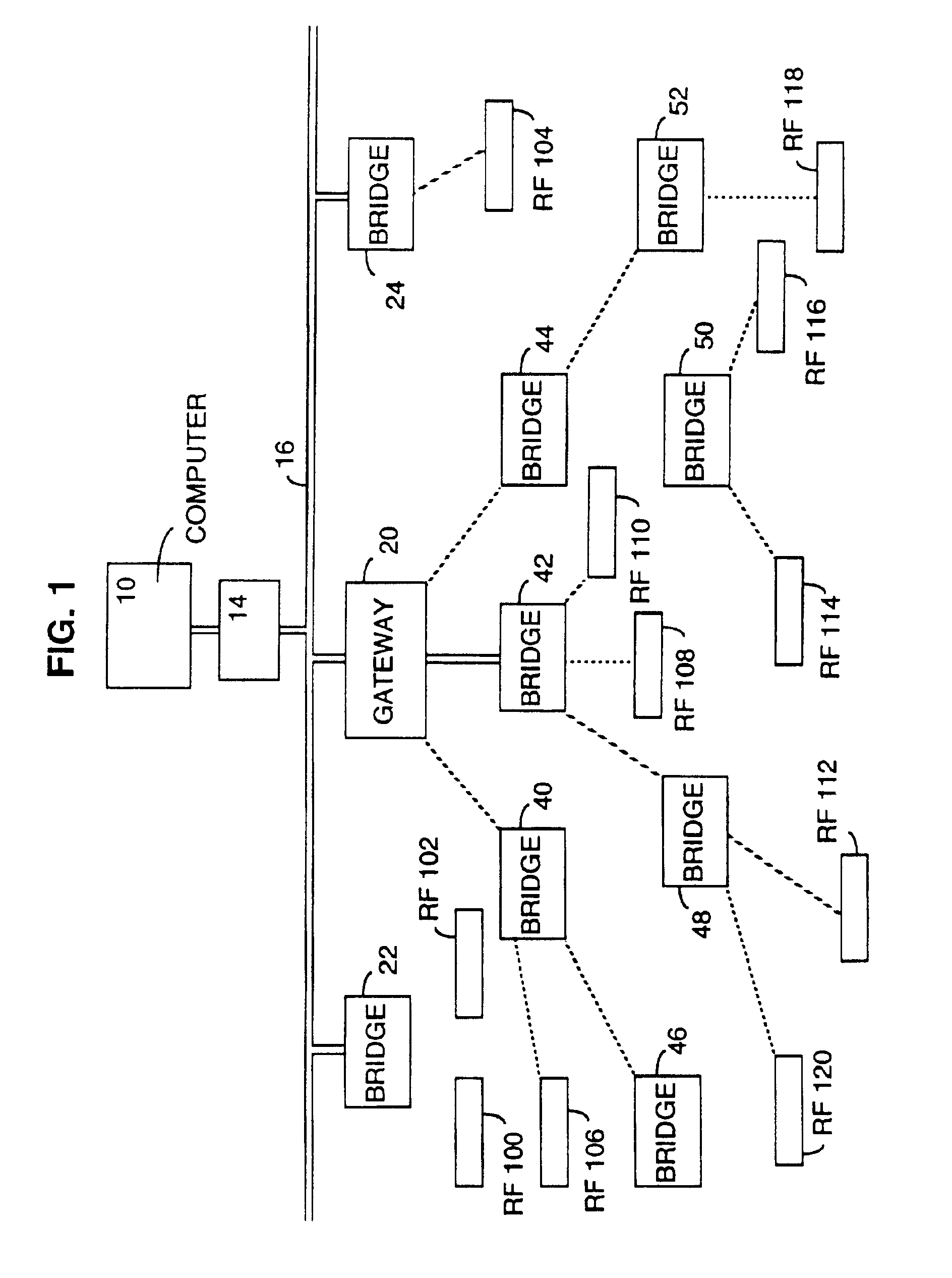
[0017]FIG. 1 is a functional block diagram of an RF data communication system. In one embodiment of the present invention, the RF data communication system has a host computer 10, a network controller 14 and bridges 22 and 24 attached to a data communication link 16. Also attached to the data communication link 16 is a gateway 20 which acts as the root node for the spanning tree of the RF data network of the present invention. A bridge 42 is attached to the gateway 20 through a hard-wired communication link and bridges 40 and 44 are logically attached to gateway 20 by two independent RF links. Additional bridges 46, 48, 50 and 52 are also connected to the RF Network and are shown in the FIG. 1. Note that, although shown separate from the host computer 10, the gateway 20 (the spanning tree root node) may be part of host computer 10.

[0018]The FIG. 1 further shows RF terminals 100 and 102 attached to bridge 22 via RF links and RF terminal 104 attached to bridge 24 via an RF link. Also,...


PUM


Abstract

An apparatus and a method for routing data in a radio data communication system having one or more host computers, one or more intermediate base stations, and one or more RF terminals organizes the intermediate base stations into an optimal spanning-tree network to control the routing of data to and from the RF terminals and the host computer efficiently and dynamically. Communication between the host computer and the RF terminals is achieved by using the network of intermediate base stations to transmit the data.

Description

CROSS-REFERENCE TO RELATED APPLICATIONS[0001]The present application is a continuation of application Ser. No. 09 / 060,287 filed Apr. 14, 1998, now U.S. Pat. No. 6,374,311 issued Apr. 16, 2002, which is a continuation of application Ser. No. 08 / 395,555 filed Feb. 28, 1995, now U.S. Pat. No. 5,740,366 issued Apr. 14, 1998, which is a continuation of application Ser. No. 08 / 255,848 filed Jun. 8, 1994, now U.S. Pat. No. 5,394,436 issued Feb. 28, 1995, which is a continuation of application Ser. No. 07 / 970,411 filed Nov. 2, 1992, now abandoned, which is a continuation-in-part of application Ser. No. 07 / 968,990 filed Oct. 30, 1992, now abandoned, which is a continuation-in-part of application Ser. No. 07 / 769,425 filed Oct. 1, 1991, now abandoned. Said application Ser. No. 07 / 968,990 is also a continuation-in-part of PCT international Application No. PCT / US92 / 08610 filed Oct. 1, 1992 and published as WO 93 / 07691 with a publication date of Apr. 15, 1993.[0002]The entire disclosures of each ...

Claims


Application Information

Patent Timeline
Patent Type & Authority Patents(United States)
IPC IPC(8): G06F1/16G06F15/02G08C17/00G08C17/02H01Q21/24H01Q1/22H01Q1/00H01Q1/24H04L1/00H04B1/69H04B1/16H04B1/38H04L29/06H04L12/56H04L12/12H04L12/28H04Q7/32H04M1/72H04M1/73H04L29/08H04L12/403H04Q7/22H04B17/00H04W40/02H04W40/08H04W40/10H04W40/24H04W40/26H04W40/30H04W40/36H04W52/02H04W68/00H04W84/12H04W88/02H04W88/06H04W88/08H04W88/14
CPCG06F1/1626G06K7/1098G08C17/02H01Q1/007H01Q1/241H01Q21/24H04B1/3833H04B1/69H04L1/0003H04L1/0007H04L1/0014H04L1/0025H04L1/0071H04L12/12H04L29/06H04L45/00H04L45/04H04L45/44H04L45/48H04L47/6225H04L49/90H04L49/9057H04W52/0225H04W68/00H04W88/06G06F15/0225H04B17/318H04B1/1615H04B17/0085H04L1/08H04L2001/0097H04W40/02H04W40/08H04W40/10H04W40/246H04W40/248H04W40/26H04W40/30H04W40/36H04W52/029H04W84/12H04W88/02H04W88/08H04W88/14H04L69/14H04L69/32H04L69/324H04L69/325H04L69/326Y02B60/50Y02D30/70H04L9/40H04L45/488
Inventor MAHANY, RONALD L.MEIER, ROBERT C.LUSE, RONALD E.
Owner AVAGO TECH WIRELESS IP SINGAPORE PTE
Why Eureka
Try Eureka