Hose clamp

a technology of hose clamps and hoses, which is applied in the direction of hose connections, packaging, haberdashery, etc., can solve the problems of screwdriver injury, difficult operation, and difficulty in tightening operation

Inactive Publication Date: 2005-05-31
CHAREST SCOTT R
View PDF16 Cites 43 Cited by
  • Summary
  • Abstract
  • Description
  • Claims
  • Application Information

AI Technical Summary

Benefits of technology

[0005]The present invention contemplates a hose clamp including a circular member with overlapping ends. The outer end of the circular member, which lies over the overlapping inner end of the circular member, has a plurality of parallel toothed projections projecting from the upper surface thereof adjacent the end thereof, with the projections lying at right angles to the circumference of the clamp. The end of the overlapping inner end of the circular member which lies under the outer end, has secured thereto a support member which extends radially outwardly from the outer surface of the overlapping inner end and passes around and projects above the outer end. An abutting member is fixedly secured to support member adjacent the end of the overlapping inner mem...

Problems solved by technology

This not only necessitates the operator having a screwdriver readily available, but also the very tightening operation is difficult, for not only must the clamp be in a position where the screw is available to the operator for tightening, but the operator must hold the clamp with one hand to keep it from rotating away, w...

Method used


Image

  • Hose clamp
  • Hose clamp
  • Hose clamp

Examples


Embodiment Construction

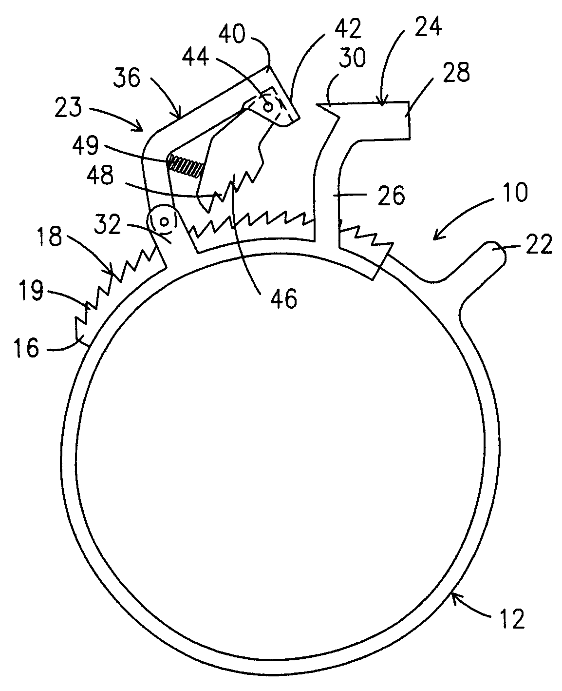
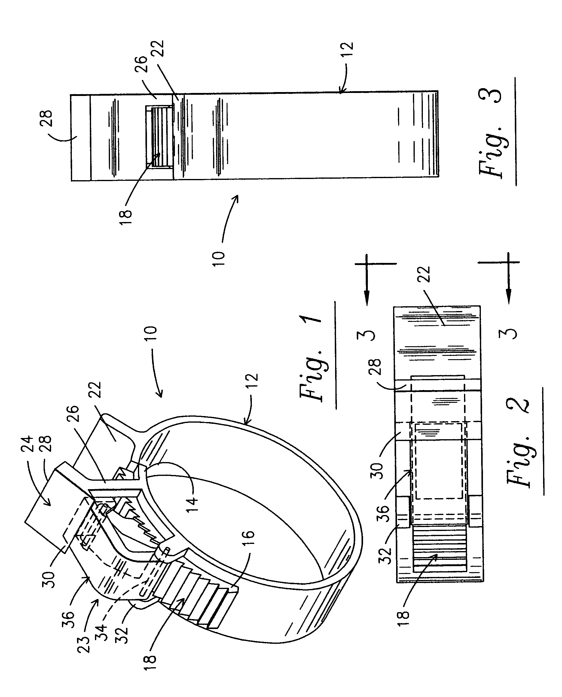
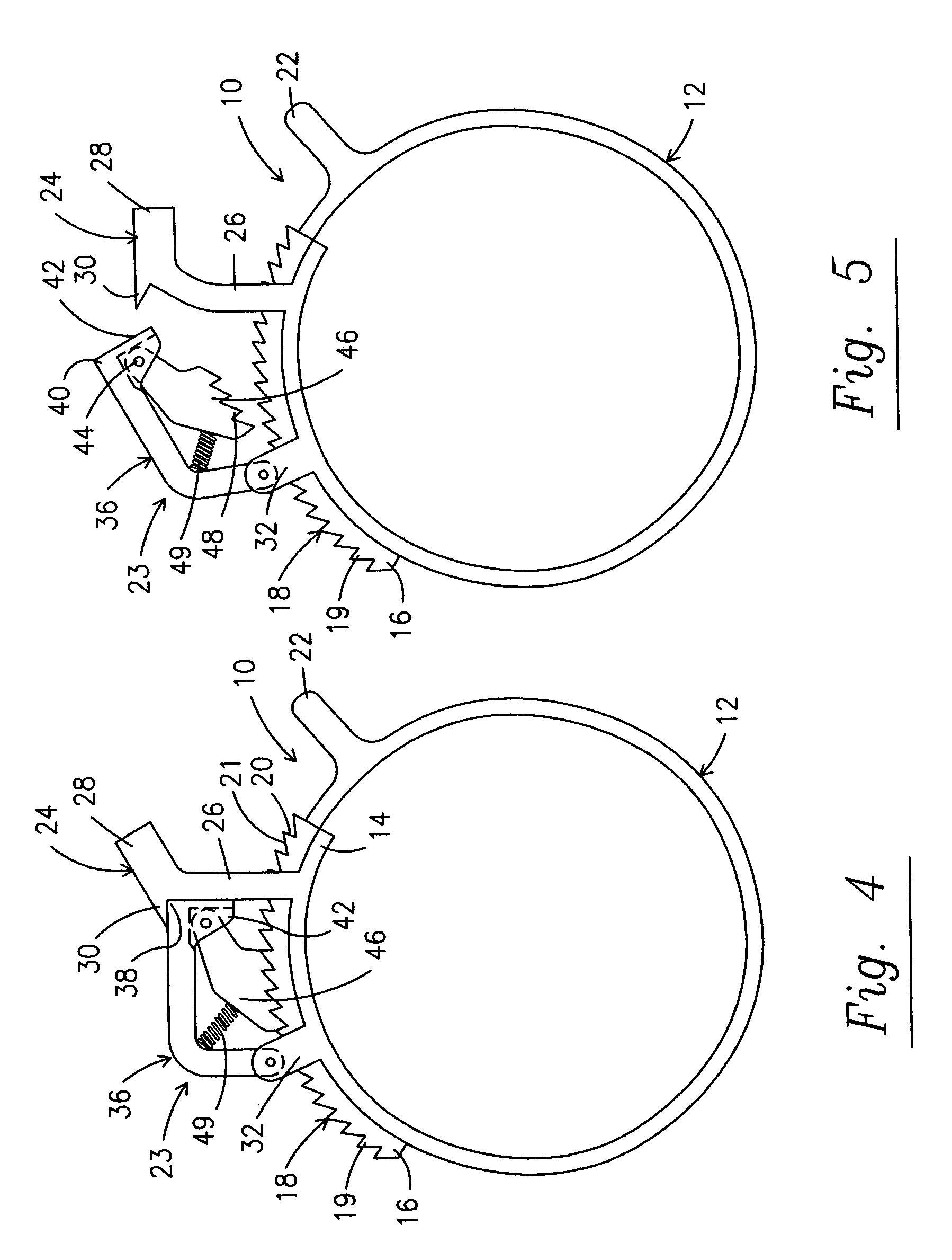
[0011]Referring now to the drawings, a hose clamp is shown generally at 10 and includes an annular member 12 having overlapping end portions, namely an overlapping inner end 14 and an overlapping outer end 16. The overlapping outer end 16 has approximately 25% of its periphery, starting from the very end thereof, provided with a series of toothed projections 18 thereon, with the width of the toothed portion 18 of the overlapping outer end 16 being reduced from the width of the remainder of the annular member 12. As seen, each tooth 19 of the toothed projections 18 has its clockwise face 20 disposed radially with respect to the center of the annular member 12, while its other face 21 is disposed in a chordal direction. Spaced slightly clockwise from the tooth projections 18, a radially projecting graspable member 22 projects outwardly from the outer surface of the annular member 12.

[0012]The overlapping inner end 14 of the of the annular member 12 lies under the outer end 16, and adj...


PUM


Abstract

A hose clamp with overlapping ends, with the outer overlapping end having a toothed portion on the outer surface thereof and the overlapping end of the inner overlapping end having a locking arrangement thereon including a pivotable locking member with toothed projections thereon cooperable with the toothed portion on the outer end and the outer end has a graspable projection for tightening the clamp.

Description

BACKGROUND OF THE INVENTION[0001]1) Field of the Invention[0002]The present invention relates to hose clamps generally and more specifically to hose clamps which can be installed by a hand operation and the hand operation automatically results tightening of the clamp.[0003]2) Description of the Prior Art[0004]Many prior art patents disclose various hose clamps, however of this variety, it appears from an investigation of the field, that two of these are most prevalent in use. One of these utilizes a screw arrangement for loosening and tightening the clamp as shown and discussed re the prior art in U.S. Pat. No. 5,664,295. This not only necessitates the operator having a screwdriver readily available, but also the very tightening operation is difficult, for not only must the clamp be in a position where the screw is available to the operator for tightening, but the operator must hold the clamp with one hand to keep it from rotating away, while tightening the screw with the screwdrive...

Claims


Application Information

Patent Timeline
IPC IPC(8): F16L33/035F16L33/02
CPCF16L33/035Y10T24/14Y10T24/1498
Inventor CHAREST, SCOTT R.
Owner CHAREST SCOTT R
Why Eureka
Try Eureka