High efficiency power amplifier with multiple power modes

a power amplifier and power mode technology, applied in the field of power amplifiers, can solve the problems of reducing the efficiency of the overall system, reducing the operation time of the device per battery charge, and consuming the most power of the overall system of the mobile phone, so as to reduce the dc power consumption, increase the size, and increase the cost

Inactive Publication Date: 2005-05-31
AVAGO TECH WIRELESS IP SINGAPORE PTE
View PDF20 Cites 48 Cited by
  • Summary
  • Abstract
  • Description
  • Claims
  • Application Information

AI Technical Summary

Benefits of technology

[0010]The present invention is a multiple power mode power amplifier that amplifies power of various levels with a bypass circuit not including switches, so that problems of power loss, increased size, and increased cost associated with conventional multiple power mode power amplifier using bypass switches may be avoided. Further, the multiple power mode power amplifier of the invention reduces DC power consumption in the low power mode, so that power added efficiency (PAE) characteristics of the power amplifier is improved and operation time of a portable electronic device (e.g., talk time of a mobile handset) equipped with the present multiple power mode power amplifier may be extended.
[0011]In one embodiment, the multiple power mode amplifier uses a variable gain amplifier as a driver to minimize power loss associated with the conventional multiple power mode power amplifier in the high power mode, so that PAE characteristics in the high power mode may be improved and poor linearity in the high power mode may be solved. In addition, improvement in sound quality and size reduction of the mobile handset may be obtained in a mobile handset or telephone equipped with the present multiple power mode power amplifier.
[0012]An embodiment of the present invention solves at least the above problems of the conventional multiple power mode power amplifier using bypass switches and provides a multiple power mode power amplifier with high efficiency that may amplify power of various levels without using bypass switches by making a path for bypassing a power stage and a path for passing through a power stage joined at an optimum point and providing an optimum impedance transformer on the path for bypassing the power stage.
[0017]In an implementation, the third impedance matching unit prevents power transferred through the impedance transformer from leaking to the power stage.
[0026]In an implementation, the third impedance matching unit prevents power transferred through the impedance transformer from leaking to the power stage.
[0034]According to another aspect, the invention includes the use of an amplifier circuit having multiple modes and without switches in a wireless transmitter or transceiver device such as a mobile telephone. The invention includes the use of an amplifier circuit having multiple modes and without switches to extend transmit time of a portable wireless device, while extending transmit time. The invention includes the use of an amplifier circuit having multiple modes and without switches to increase the battery life of a portable wireless device. The invention includes the use of an amplifier circuit having two or more modes without switches to operate in a low power or a high power mode depending on a distance to a receiving antenna, thus improving efficiency and reducing power consumption. The invention includes the use of a change in an impedance of a power stage to change from a low or high power, or vice versa, without using switches. The invention includes the use of impedance network to change from one power mode to another power mode for an amplifier without switches.

Problems solved by technology

As can be appreciated, these are difficult goals to reconcile; if the power drain of a device remains the same and the battery is smaller, operating time of the device per battery charge becomes shorter.
In a conventional mobile handset, the radio frequency (RF) power amplifier consumes most of the power of the overall system of the mobile handset.
Thus, low efficiency of the RF power amplifier degrades the efficiency of the overall system, drains the battery more rapidly, and thus reduces the talk time.
However, the multiple power mode power amplifier with switches (e.g., PIN diodes) is relatively costly to manufacture and the switches reduce efficiency somewhat because they may have negative gain (e.g., 1dB gain per switch).
Power losses caused by switching operations at the bypass switching circuits causes a reduction of output power and the reduction of output power causes reduction of efficiency of the multiple power mode power amplifier.
Further, there is another problem in that an adjacent channel power ratio (ACPR) gets worse.
Furthermore, the size of the entire system gets larger due to bypass switching circuits themselves and the complex logical control circuit additionally added for controlling the bypass switching circuits, so that the conventional multiple power mode power amplifier is considered as regressive considering a trend towards a smaller-sized mobile handset.
Also the enlarged size of the entire system is disadvantageous in price competitiveness, particularly since the switches are expensive components.

Method used


Image

  • High efficiency power amplifier with multiple power modes
  • High efficiency power amplifier with multiple power modes
  • High efficiency power amplifier with multiple power modes

Examples


Embodiment Construction

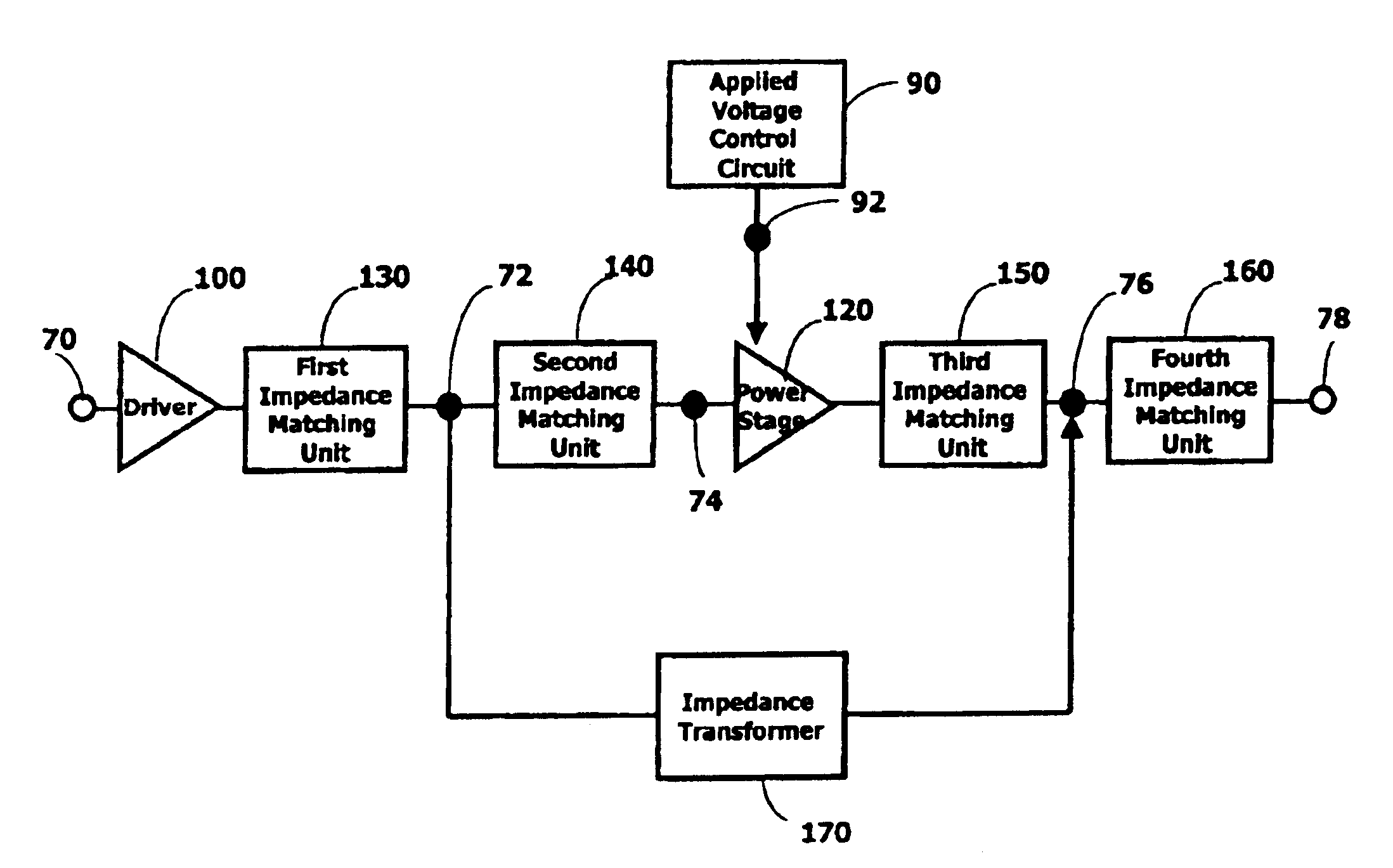
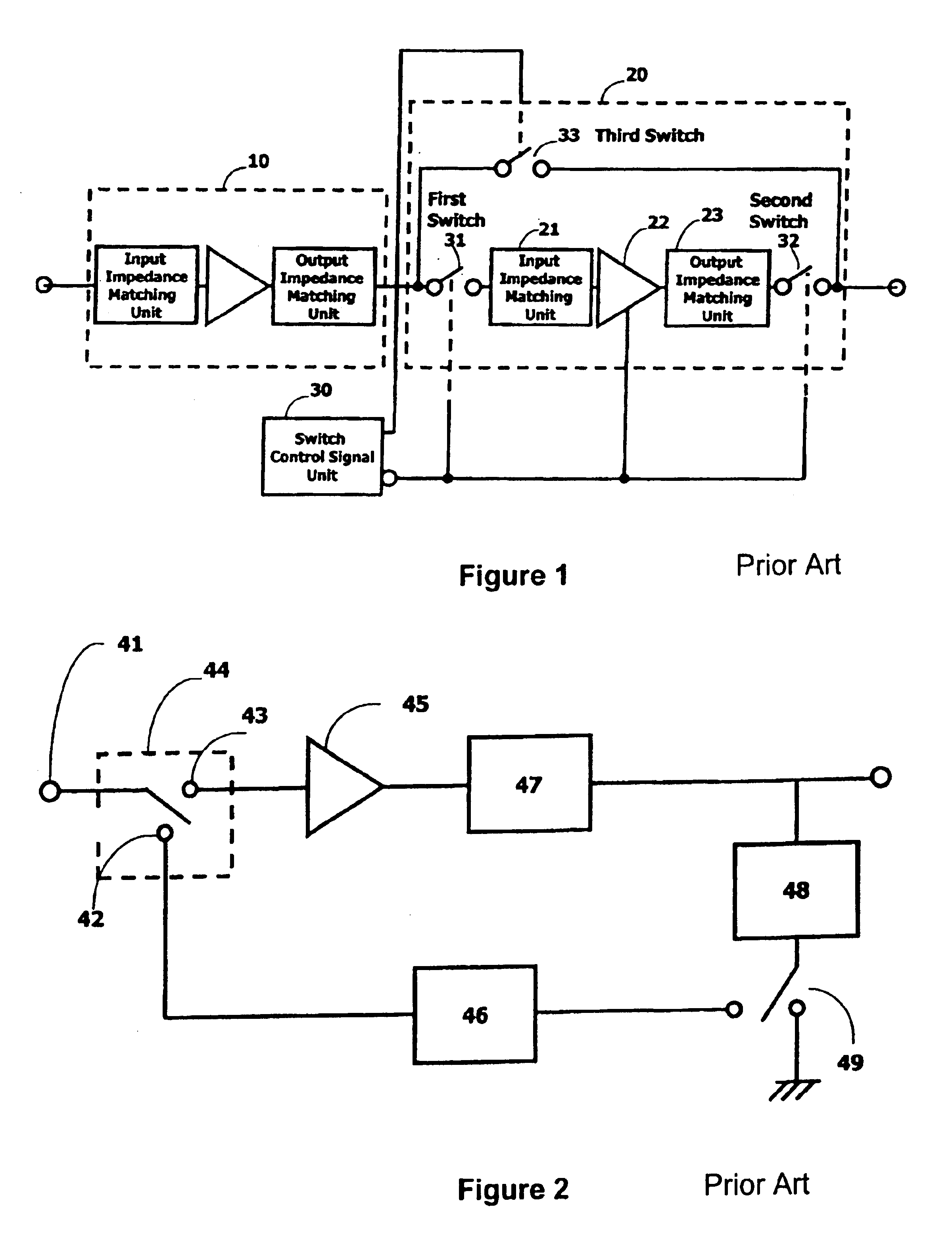
[0046]FIG. 1 illustrates a conventional multiple power mode power amplifier using bypass switches or bypass switch circuits. The multiple power mode power amplifier illustrated in FIG. 1 is configured using three bypass switch circuits.

[0047]If the power amplifier is operated in the high power mode, both a first switch 31 and a second switch 32 are closed and a third switch 33 is open, so that output of a driver 10 including an impedance matching unit is input into a power stage 22 (or power amplifying component). In contrast, if the power amplifier is operated in the low power mode, both the first switch 31 and the second switch 32 are open and the third switch 33 is closed, so that output of the driver 10 including the impedance matching unit bypasses the power stage 22.

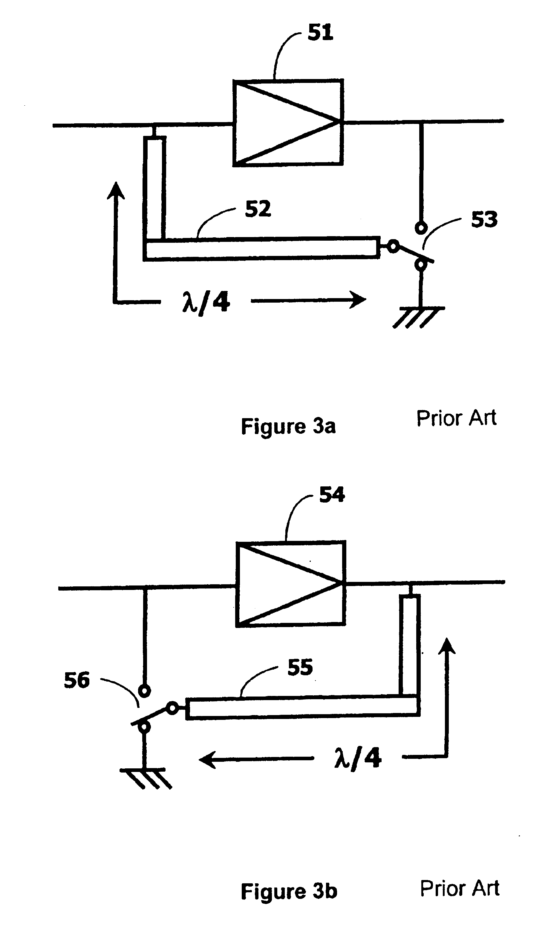
[0048]The multiple power mode amplifier illustrated in FIG. 1 has disadvantages in that the size of the entire system increases and power loss of the entire system increases due to power loss of the bypass switch c...


PUM


Abstract

A multiple power mode amplifier provides a low and a high power mode without using switches. This amplifier may be used in RF applications such as mobile telephones. In the low power mode, the power consumption of the amplifier is reduced, which will increase operation time, especially important for battery-operated devices. In one implementation, the amplifier includes a number of impedance matching network units (130, 140, 150, and 160), impedance transformer (170), and a power stage (120).

Description

CROSS-REFERENCE TO RELATED APPLICATIONS[0001]This application claims priority under 35 U.S.C. § 119 to Korean patent application number 2003-208, filed on Jan. 3, 2003, which is incorporated by reference, along with all other references cited in this application.BACKGROUND OF THE INVENTION[0002]The present invention relates to a power amplifier, especially a radio frequency (RF) amplifier used in mobile handset and other battery-powered applications (e.g., portable wireless devices, personal digital assistants (PDAs), notebook computers, and others). More particularly, the present invention relates to a multiple power mode power amplifier with high efficiency appropriate for amplifying power corresponding to various output power levels without using bypass switching circuits.[0003]Mobile handsets or mobile telephones (also sometimes called cell phones) for wireless communication services are becoming smaller and lighter. This also means a size of the battery, which is a typically a ...

Claims


Application Information

Patent Timeline
Patent Type & Authority Patents(United States)
IPC IPC(8): H03F1/00H03F1/02H03F1/56H04L12/20
CPCH03F1/0211H03F1/0277H03F1/56H03F3/72H03F2203/7239H03F2200/318H03F2203/7231H04L12/16
Inventor KIM, JUNGHYUNLEE, DAEHEEJUNG, SANGHWAKWON, YOUNGWOO
Owner AVAGO TECH WIRELESS IP SINGAPORE PTE
Why Eureka
Try Eureka