Steering column for motor vehicle

Active Publication Date: 2005-06-07
NSK LTD
View PDF10 Cites 24 Cited by
  • Summary
  • Abstract
  • Description
  • Claims
  • Application Information

AI Technical Summary

Benefits of technology

[0009]It is therefore an object of this invention to provide a steering column equipped with a highly reliable, easy-to-operate clamp / unclamp mechanism. The clamp / unclamp mechanism of either of the telescopic mechanism and the tilting mechanism has no part jutting out of the steering column and is operated by a single lever located near the steering wheel.
[0010]The telescopic mechanism, including the steering column, is clamped with the frictional force. Since clamping is done by utilizing the frictional force, the clamp section is likely to slip when a great force is applied. Passenger cars in these years have come to be equipped with an air bag system as standard equipment. The air bag system is designed on the premise that the steering wheel is supported with stability when the air bag is operated. Therefore, it has been demanded that the steering wheel will not move at the time of the secondary collision, that is, the clamp section of the telescopic mechanism will not slip with a force resulting from the secondary collision.
[0011]In order to meet the demand stated above, therefore, it is another object of this invention to provide the steering column that the clamp section will not easily slip with the force caused by the secondary collision.

Problems solved by technology

Since clamping is done by utilizing the frictional force, the clamp section is likely to slip when a great force is applied.

Method used


Image

  • Steering column for motor vehicle
  • Steering column for motor vehicle
  • Steering column for motor vehicle

Examples


first embodiment

[0048]General Outline

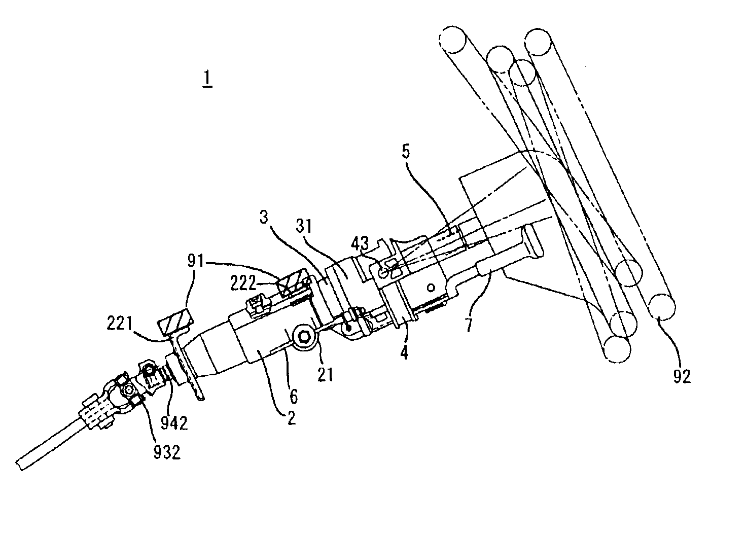
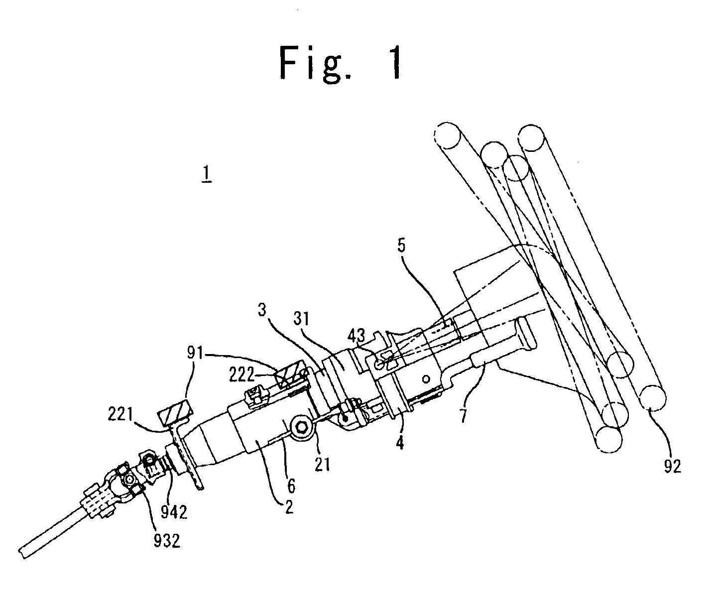
[0049]FIG. 1 is an outside view of a steering column 1 according to the first embodiment of this invention. The steering column 1 has a fixed column member 2, a moving column member 3, a column head 31, a tilt head 4, a wheel shaft 5, a column clamp 21, a tilt head clamp 41 (see FIG. 2), an control lever 7, and a mechanical transmission apparatus.

[0050]The fixed column member 2 is fitted with mounting sections 221 and 222 for mounting to the vehicle body 91. On the fixed column member 2 the moving column member 3 is supported unrotatably around the center axis and movably in the direction of the center axis. The column head 31 is mounted on one end of the moving column member 3. On the column head 31, the tilt head 4 is supported in such a manner that it can tilt on the center of a tilt center axis 43. On the tilt head 4 the wheel shaft 5 is rotatably supported. A steering wheel 92 is fixed on one end of the wheel shaft 5.

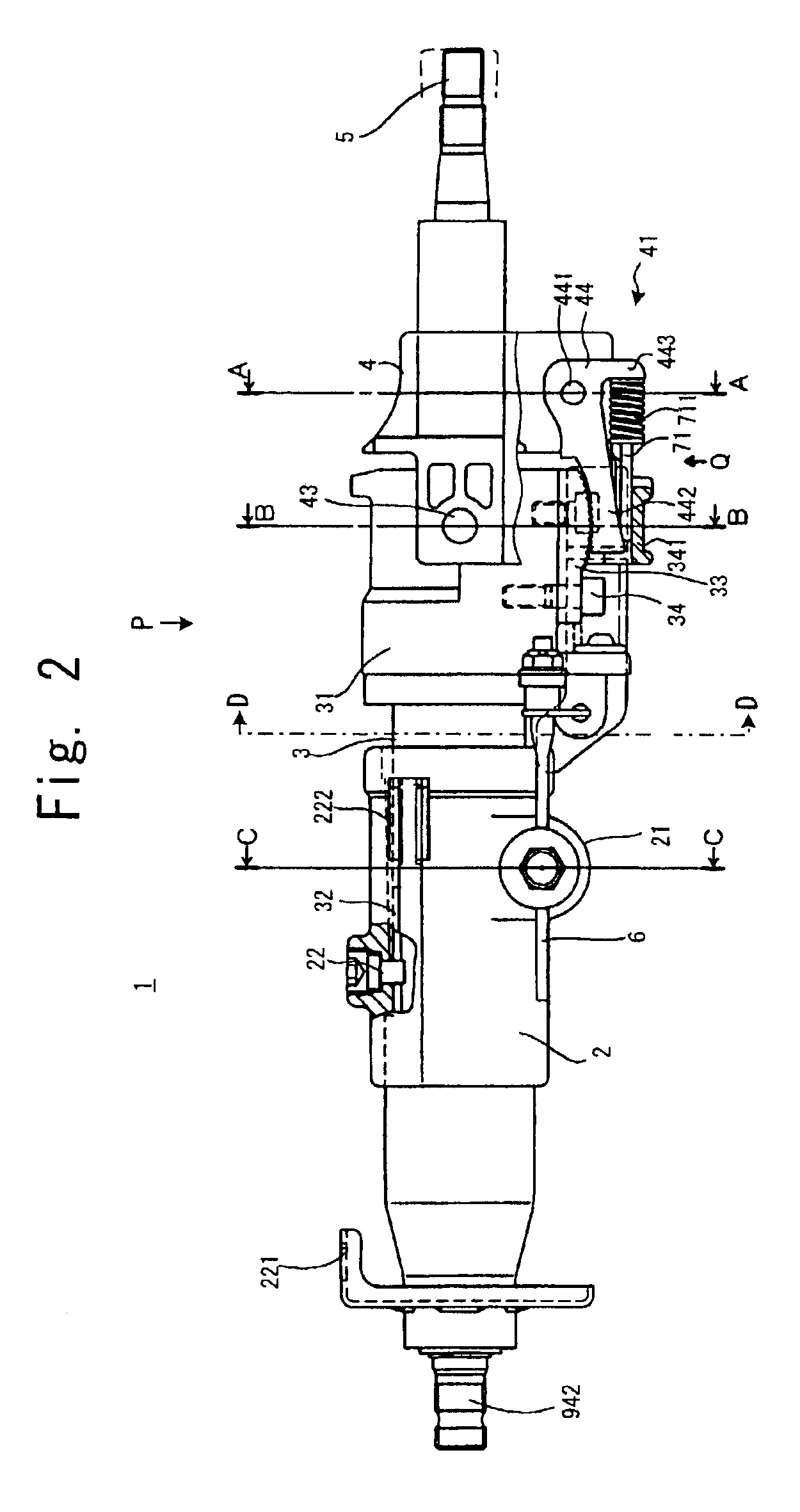
[0051]On the column head 31, a column cl...

second embodiment

[0086]The steering column 1 of the second embodiment, except the structure of the control lever 7, has a structure common to that of the steering column of the first embodiment. To avoid redundancy of explanation, only the control lever 7 and related structures which are different from the first embodiment will be explained, using the same reference numerals as those used in the explanation of the first embodiment.

[0087]FIG. 12 is a top view, partly cut away, of the steering column 1 according to the second embodiment. FIG. 12 corresponds to FIG. 3 in the first embodiment. The control lever 7 in the second embodiment has a control lever body 705 and a control lever end 701 pivotally supported thereon. The control lever end 701 is foldable in between the operating position and the retreat position. In the operating position, the control lever 7 is operable by other fingers with the thumb left on the steering wheel 92. In the retreat position, the control lever is apart from the steer...

third embodiment

[0091]The steering column 1 of the third embodiment has a structure substantially common to the steering column of the first embodiment excepting the provision of the cowl 35 and the structure of the control lever 7. To avoid redundancy of explanation, only the cowl 35, the control lever 7 and related structures which are different from the first embodiment will be explained; the same reference numerals as those used in the explanation of the first embodiment will be used.

[0092]FIG. 13 is a top view, partly cut away, of the steering column 1 according to the third embodiment. FIG. 13 corresponds to FIG. 3 in the first embodiment. The cowl 35 is a cover for covering the tilt head 4 and the moving column member 3, and is fixed on the tilt head 4. The cowl 35 has a shaft hole 3 through which the wheel shaft 5 is mounted, and a lever hole 352 through which the control lever 7 is mounted.

[0093]In the side of the cowl 35, a dent is formed so that a part of the control lever end 701 folded...


PUM


Abstract

A steering column is structured such that a clamp / unclamp mechanism of a telescopic mechanism and a tilting mechanism can be operated by a single control lever located in the vicinity of a steering wheel, and that no part juts out of the steering column to improve reliability and controllability. When the control lever is pulled to rock on the center of the lever center axis, a tilt head is unclamped, while the rocking motion of the control lever turns a pusher plate, thereby pushing a pusher rod and also turning a column clamp shaft through a rocking arm. With the rotation of the column clamp shaft, the clamp is released to allow a column head to move. Since the column clamp shaft turns parallelly with the direction of movement of the column head, the column head can be clamped / unclamped regardless of its position.

Description

[0001]This application is based on applications No. 2002-146694, No. 2002-245636, and No. 2002-273484 filed in Japan, the contents of which are hereby incorporated by reference.BACKGROUND OF THE INVENTION[0002]1. Field of the Invention[0003]This invention relates to a steering column, and more particularly, to a steering column for motor vehicle having a telescopic mechanism and a tilting mechanism.[0004]2. Description of Related Art[0005]The telescopic mechanism and the tilting mechanism of the steering column aim at adjusting the back-and-forth position and tilt angle of a steering wheel to the easiest-to-manipulate position according to the driver's body form and taste.[0006]The telescopic mechanism and the tilting mechanism have a clamp / unclamp mechanism for adjusting the level and tilt angle of the steering wheel. When the adjustment is made, the clamp / unclamp mechanism is cancelled once, and is operated to clamp again after the adjustment.[0007]The adjustment of forward-and-ba...

Claims


Application Information

Patent Timeline
IPC IPC(8): B62D1/18B62D1/184B62D1/187
CPCB62D1/184
Inventor SATO, KENJIMATSUMOTO, SAKAE
Owner NSK LTD
Why Eureka
Try Eureka