Four function electrical rocker switch

a rocker switch and four-function technology, applied in the field of electric switches, can solve the problems of increasing the number of gang boxes in which such switches can be placed, increasing the number of electrical cables extending through existing walls, and the heat produced by these closely placed conductors may exceed the safe level

Inactive Publication Date: 2005-06-07
LEVITON MFG
View PDF7 Cites 6 Cited by
  • Summary
  • Abstract
  • Description
  • Claims
  • Application Information

AI Technical Summary

Problems solved by technology

However, much of this equipment is placed in existing structures where it is difficult to increase the number of gang boxes in which such switches can be placed or increase the number of electrical cables extending through existing walls.
Thus, there are six conductors crowded into a single gang box which increases the possibility of physical contact between individual conductors or between the conductors and the gang box which may result in short-circuits.
Also, the heat produced by these closely placed conductors may exceed safe levels.

Method used


Image

  • Four function electrical rocker switch
  • Four function electrical rocker switch
  • Four function electrical rocker switch

Examples


Embodiment Construction

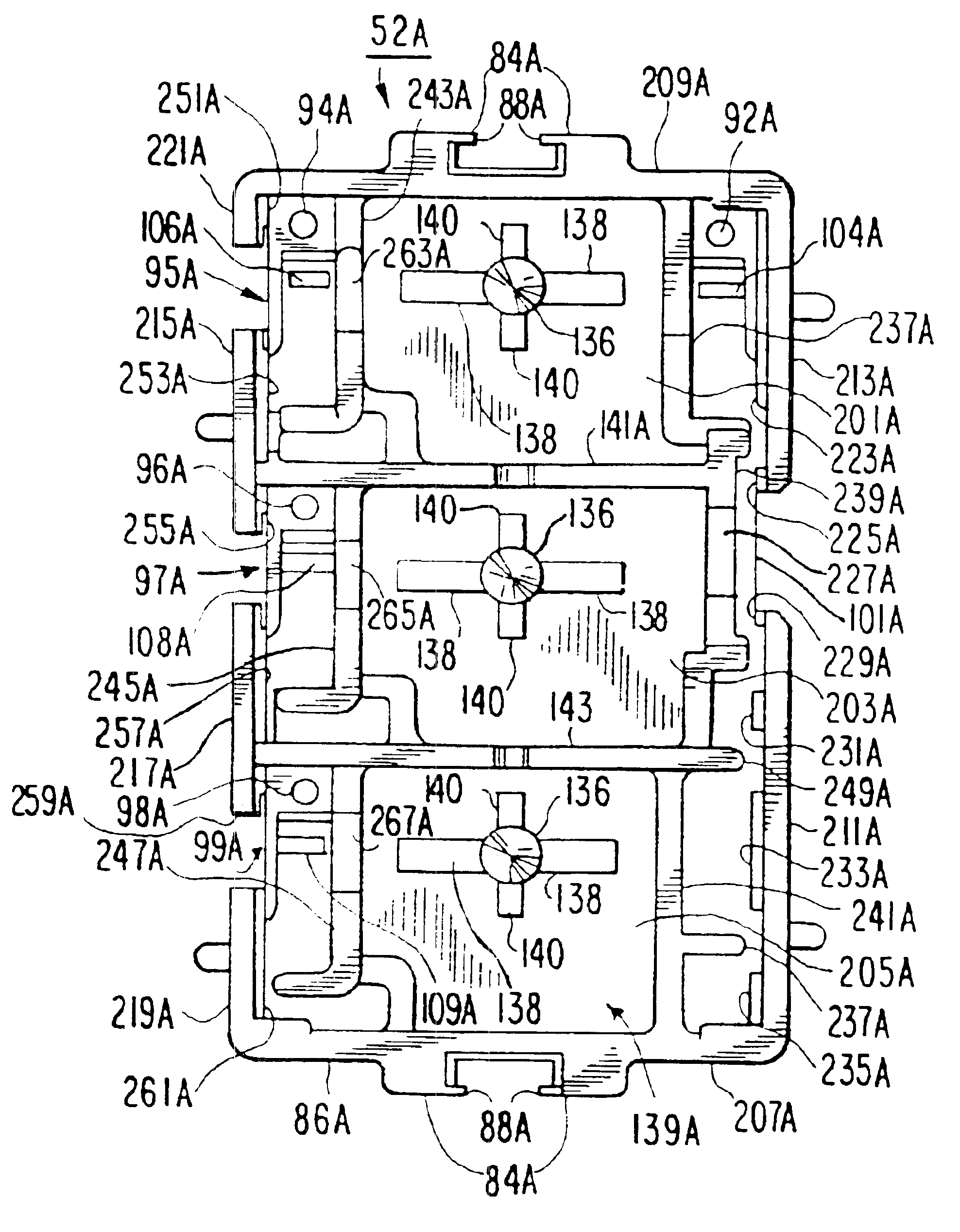
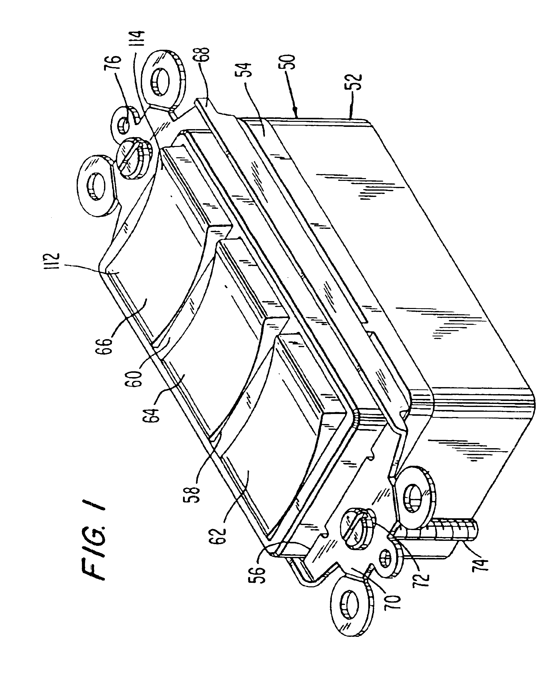
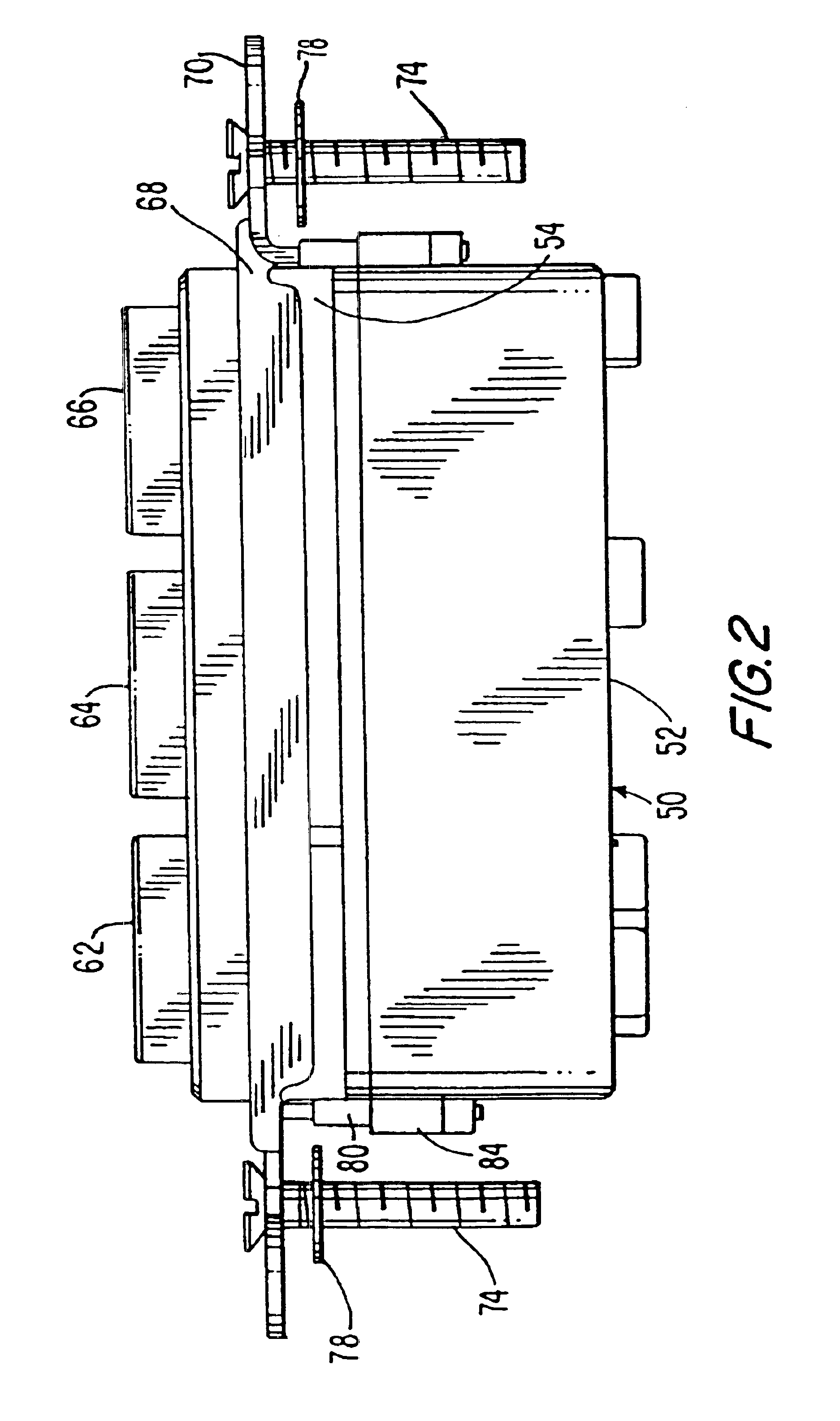
[0055]Turning now to FIGS. 1, 2, 3 and 4, there is shown the exterior of a four function electrical rocker switch 50 constructed in accordance with the concepts of the invention. A base 52, as will be described below, contains the various fixed and movable contacts and the operating means therefore. Fixed to the base 52 is a cover 54 which contains three apertures 56, 58 and 60 (see FIG. 13) through which project three rockers 62, 64 and 66, respectively. A strap 68 surrounds the cover 54 and assembles it to the base 52 and provides for mounting the switch 50 to the mounting ears of a gang box (not shown) as is well known in the art. Strap 68 has flat portions 70 at each end through which extend apertures 72 to receive mounting screws 74 to fasten switch 50 to the ears of a gang box (not shown). Threaded apertures 76 accept the threaded fasteners of a cover plate (not shown) to finish the installation of the switch 50 to a gang box. Squares of insulation 78 on fasteners 74 insulate ...


PUM


Abstract

A four function electrical rocker switch has two single pole, single throw on / off sections having their movable contact arms coupled to a single electrical line and their screw terminal fixed contacts connected to individual circuits. The two switch sections are independently operated. A third rocker switch is a single pole, double throw switch with a center-off position. The third switch can be operated to either of two positions to operate either one of two independent circuits or can be left in the center-off position not engaging either circuit. A five function electrical rocker switch can be made up of one section having a single pole, single throw on / off switch and two sections with single pole, double throw switches which each have a center-off position.

Description

[0001]This application is a continuation-in-part of application for U.S. Letters Patent application having Ser. No. 09 / 235,785, which issued on Jan. 15, 2002 as U.S. Pat. No. 6,339,201 which was a Continued Prosecution of application having Ser. No. 09 / 235,785 filed on Jan. 22, 1999 and abandoned on Aug. 22, 2000 which was a continuation-in-part of application having Ser. No. 08 / 865,921 filed on May 30, 1997 and abandoned on Jan. 24, 1999.BACKGROUND OF THE INVENTION[0002]1. Field of the Invention[0003]The invention deals with electrical switches, and more particularly, with multiple function electrical switches that can be placed in a single, standard gang box.[0004]2. Description of the Prior Art[0005]As the use of electrical equipment in the home and commercial establishments increases, there is a need to increase the number of electrical switches used for controlling or supplying electrical power to such equipment. However, much of this equipment is placed in existing structures ...

Claims


Application Information

Patent Timeline
Patent Type & Authority Patents(United States)
IPC IPC(8): H01H23/00H01H1/58H01H1/00H01H23/16
CPCH01H1/5833H01H23/00H01H23/168
Inventor BALABAN, DAVID B.TUFANO, ANTHONY
Owner LEVITON MFG
Why Eureka
Try Eureka