Disc cartridge and disc recording and/or reproducing apparatus

Inactive Publication Date: 2005-08-23
SONY CORP
View PDF7 Cites 0 Cited by
  • Summary
  • Abstract
  • Description
  • Claims
  • Application Information

AI Technical Summary

Benefits of technology

[0013]The present invention is proposed in view of the above-mentioned circumstances and is to smoothly slide the tray even if a moment in a tray rotation direction is applied to the hook of the tray, and easily carry out the dimensional management of the parts and the like.
[0015]In the disc cartridge according to the present invention, the fitting between the guide rail disposed in either of the tray or the case and the fitting unit disposed in the other tray or case enables the tray to be smoothly taken in and out. In addition, the slide guide is disposed in substantial series with the direction, in which the tray is taken in and out, with respect to the operating unit (hook) of the tray. Thus, even if a moment in the tray inclination direction is applied to the operating unit when the tray is taken in and out, the inclination of the tray can be minimized to smoothly slide the tray. Also, as compared with the conventional case in which the slide of the tray is guided between the left and right sides of the cartridge case, the width of the guide plane can be reduced to thereby make a management of a part size and the like easier. Furthermore, in the disc cartridge according to the present invention, the slide guide is composed of the grooved concave portion on the reverse side of the tray and the ligulate convex portion on the cartridge case side. Thus, the structure of the slide guide is simple. Also, when the tray and the cartridge case are molded from plastic, the concave portion and the convex portion can be formed integrally with them. In addition, the divergently tapered concave portion insertion guide (tapered surface) is disposed at the end of the grooved concave portion. Thus, due to the guide, the convex portion can be inserted into the grooved concave portion easily and surely.
[0016]In the disc recording and / or reproducing apparatus according to the present invention, the tray can be smoothly slid by guiding the slide of the tray not only in the cartridge case but also in the elevator. When the tray is pulled out of the disc cartridge, the ligulate convex portion serving as the slide guide formed on the elevator side is introduced into the grooved concave portion formed on the reverse side of the tray. Accordingly the convex portion guides the slide of the tray.
[0017]Furthermore, the disc recording and / or reproducing apparatus according to the present invention, the divergently tapered convex portion insertion guide formed at the end of the grooved concave portion formed on the reverse side of the tray enables the ligulate convex portion to be inserted into the grooved concave portion easily and surely. In addition, when the trays are pulled into the elevator by the predetermined amount, the ligulate convex portion serving as the slide guide formed on the elevator side is put in the notch hole made in the substantial center of the grooved concave portion. Accordingly, the tray can be lowered correspondingly to it. Thus, after the disc supported on the tray is placed on the disc table, the tray is lowered, which leads to the non-contact state between the disc and the tray. Then, the disc can be rotated.

Problems solved by technology

(1) If a moment in a direction indicated by an arrow M (a direction in which the tray is inclined to a direction A where it is taken in and out) is applied in pulling the hook 205 of the tray 203, the side 203a of the tray 203 is pushed against the side 204a of the cartridge case 204. Thus, a smooth slide of the tray 203 is impeded. In the worst case, the tray 203 is caught by the side 204a, and it is stopped.
(2) Since a distance L between the guide planes is long, a dimensional tolerance between the guide planes is large. Thus, in order to attain an excellent guide effect, management of components is difficult.

Method used


Image

  • Disc cartridge and disc recording and/or reproducing apparatus
  • Disc cartridge and disc recording and/or reproducing apparatus
  • Disc cartridge and disc recording and/or reproducing apparatus

Examples


Embodiment Construction

[0056]A disc cartridge and a disc recording and / or reproducing apparatus according to the present invention will be described below by using a disc auto-changer and a disc cartridge used therein as an example. This description will be divided into respective items of: (1) an explanation of an outline of the disc auto-changer; (2) an explanation of the disc cartridge; (3) an explanation of an elevator; (4) an explanation of an elevating control mechanism; (5) an explanation of a loading mechanism; (6) an explanation of a disc chucking mechanism; (7) an explanation of an entire operation of the disc auto-changer; and (8) an explanation of another embodiment of the elevating control mechanism. Then, the divided items are described in the above-mentioned order.

(1) Explanation of Outline of Disc Auto-Changer

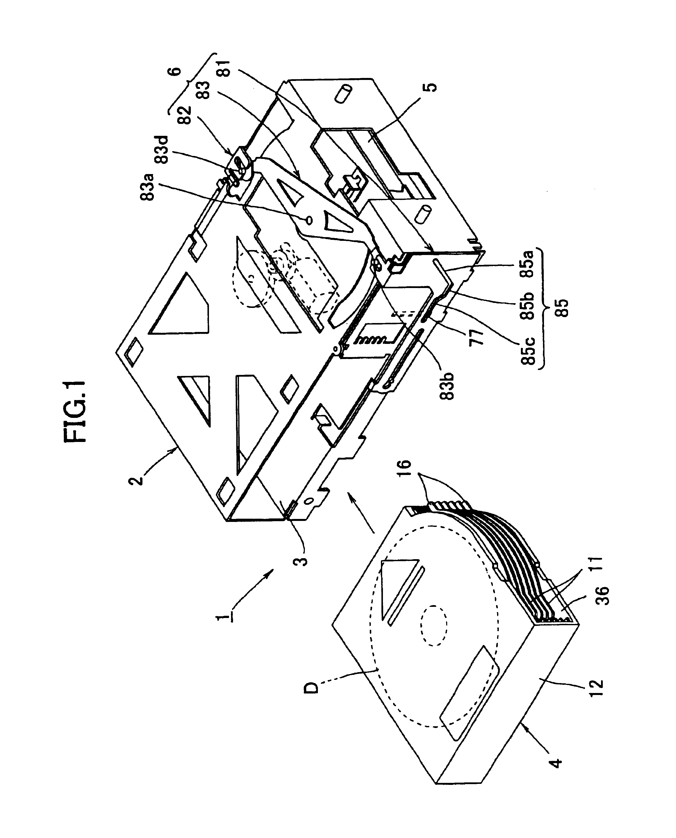
[0057]FIG. 1 is a perspective view of a disc auto-changer 1. The disc auto-changer 1 is provided with: a disc cartridge 4 having a plurality of disc placing trays 11 to be loaded into...


PUM


Abstract

A disc cartridge provided with: a plurality of trays, each of which can place a disc; and a case where those trays can be taken in and out of an opening, wherein an operating unit is disposed in each of the trays, a guide rail is disposed in either one of the trays and the case in a direction in which the trays are taken in and out of the case, and a fitting unit is disposed in the other of the trays and the case so as to be fit in the guide rail in order to guide the trays along this guide rail, and when the trays are taken in and out of the case, they can be smoothly taken in and out in such a way that the trays are not caught by the case, and a disc recording and / or reproducing apparatus having such a disc cartridge.

Description

[0001]This application is a Division of application Ser. No. 09 / 987,552 Filed on Nov. 15, 2001, now U.S. Pat. No. 6,600,702.CROSS REFERENCES TO RELATED APPLICATIONS[0002]The present document is based on Japanese Priority Document JP 2000-350520, filed in the Japanese Patent Office on Nov. 17, 2000, the entire contents of which being incorporated herein by reference.BACKGROUND OF THE INVENTION[0003]1. Field of the Invention[0004]The present invention relates to: a disc cartridge provided with a plurality of trays each holding a disc, and a cartridge case assembled so as to enable those trays to be taken in and out, in which an operating unit disposed in the tray is drawn or pressed to thereby take the tray in and out; and a disc recording and / or reproducing apparatus (hereafter, referred to as a disc auto-changer) for recording on and / or reproducing from the disc on the tray by using the disc cartridge.[0005]2. Description of the Related Art[0006]A disc cartridge shown in FIG. 32 is ...

Claims


Application Information

Patent Timeline
IPC IPC(8): G11B17/30G11B17/22
CPCG11B17/30G11B17/22
Inventor SATO, MASAHIRONITTA, IKUOTAKAHASHI, YUJI
Owner SONY CORP
Why Eureka
Try Eureka