Volute pump

Active Publication Date: 2018-02-22
EBARA CORP
View PDF18 Cites 1 Cited by
  • Summary
  • Abstract
  • Description
  • Claims
  • Application Information

AI Technical Summary

Benefits of technology

The invention allows for a fibrous substance to smoothly slide on the leading edge of a sweep-back vane and transfer into a groove without getting caught there. The front-side curved surface pushes the fibrous substance into the groove, and it is then transferred to the volute chamber along the groove by the rotation of the impeller. The fibrous substance is then discharged from the discharge port. This results in a more efficient transfer of the fibrous substance to the volute chamber, leading to better performance of the device.

Problems solved by technology

When the fibrous substances are accumulated on a vane of an impeller, the pump may be clogged.

Method used


Image

  • Volute pump
  • Volute pump
  • Volute pump

Examples


Embodiment Construction

[0044]Embodiments of the present invention will be described below with reference to the drawings. The same reference numerals are used in FIGS. 1 through 16 to refer to the same or corresponding elements, and duplicate descriptions thereof will be omitted.

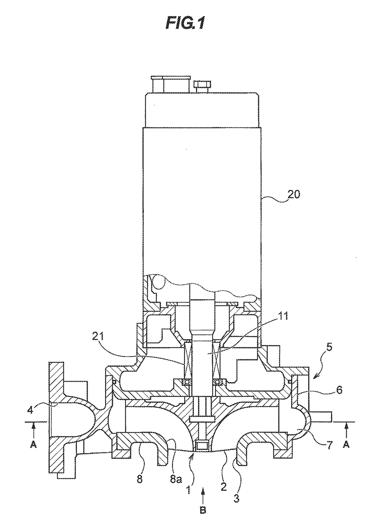
[0045]FIG. 1 is a schematic cross-sectional view of a volute pump according to an embodiment of the present invention. The volute pump shown in FIG. 1 is, for example, used for delivering a liquid, such as sewage water flowing through a sewage pipe. As shown in FIG. 1, the volute pump includes an impeller 1 which is fixed to an end of a rotational shaft 11, and an impeller casing 5 which houses the impeller 1 therein. The rotational shaft 11 is rotated by a motor 20, and the impeller 1 is rotated in the impeller casing 5 together with the rotational shaft 11. A mechanical seal 21 is disposed between the motor 20 and the impeller 1. This mechanical seal 21 prevents the liquid from entering the motor 20.

[0046]The impeller casing 5 i...


PUM


Abstract

A volute pump for delivering a liquid containing fibrous substances. The volute pump includes an impeller (1) rotatable together with a rotational shaft (11), and an impeller casing (5) having a suction port (3) and a volute chamber (7). A groove (18), extending from the suction port (3) to the volute chamber (7), is formed in an inner surface of the impeller casing (5). The impeller (1) includes a hub (13) to which the rotational shaft (11) is fixed, and a sweep-back vane (2) extending helically from the hub (13). The sweep-back vane (2) includes a leading edge portion (2a) extending helically from the hub (13), and a trailing edge portion (2b) extending helically from the leading edge portion (2a). The leading edge portion (2a) has a front-side curved surface (2e) extending from an inner end (2c) to an outer end (2d) of the leading edge portion (2a).

Description

TECHNICAL FIELD[0001]The present invention relates to a volute pump, and more particularly to a volute pump for delivering a liquid containing fibrous substances.BACKGROUND ART[0002]Conventionally, a volute pump has been used for delivering a liquid, such as sewage water flowing through a sewage pipe. Such sewage water may contain fibrous substances, such as string, or textile. When the fibrous substances are accumulated on a vane of an impeller, the pump may be clogged. Therefore, in order to prevent the fibrous substances from being accumulated on the impeller, there is a volute pump which includes an impeller having sweep-back vane (see Patent document 1).[0003]FIG. 17 is a cross-sectional view showing a volute pump which includes an impeller having sweep-back vanes. As shown in FIG. 17, an impeller 100 includes a plurality of sweep-back vanes 101. The impeller 100 is fixed to a rotational shaft 102, and is housed within an impeller casing 105. The impeller 100 is rotated in a di...

Claims


Application Information

Patent Timeline
IPC IPC(8): F04D29/70F04D7/04F04D29/24
CPCF04D29/708F04D7/04F04D29/245F04D7/045F04D29/2288F04D29/4273F05D2240/303F05D2250/71
Inventor KAWAI, MASAHITOSAKACHO, HIROMIOBUCHI, MASASHIUCHIDA, HIROSHIISONO, MIHOTOKAIRIN, KENTA
Owner EBARA CORP
Why Eureka
Try Eureka