
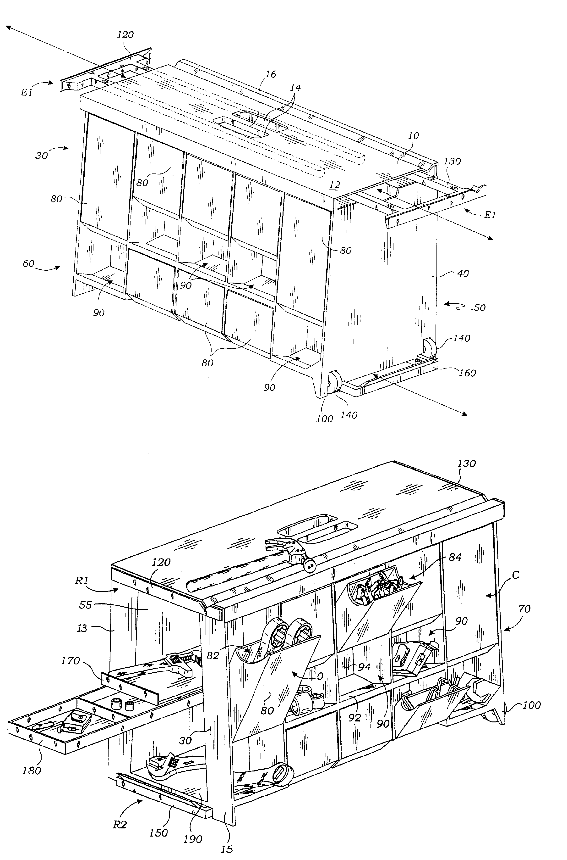
Portable combination toolbox, workbench, and dispensing crib

a combination toolbox and workbench technology, applied in the field of portable toolboxes, can solve the problems of not teaching such a stable and mobile footing apparatus when at rest, and not teaching

Inactive Publication Date: 2005-08-30
HAHN RICHARD DUK WONG
View PDF20 Cites 48 Cited by
  • Summary
  • Abstract
  • Description
  • Claims
  • Application Information

AI Technical Summary

Benefits of technology

[0033]A further objective is to provide such an invention capable of both closed drawer storage and open bin storage in a manner wherein items stored therein are prevented from falling out of the drawers and bins when the invention is subject to vibration.

Problems solved by technology

The prior art teaches the use of portable combination workbenches and toolboxes, but does not teach such an apparatus with stable footing when at rest and mobile footing when raised for being pulled-along.
The prior art also does not teach such a combination with tool and hardware storage facility tilted laterally for improved item security when being moved.

Method used


Image

  • Portable combination toolbox, workbench, and dispensing crib
  • Portable combination toolbox, workbench, and dispensing crib
  • Portable combination toolbox, workbench, and dispensing crib

Examples


Embodiment Construction

[0040]The above described drawing figures illustrate the invention in at least one of its preferred embodiments, which is further defined in detail in the following description.

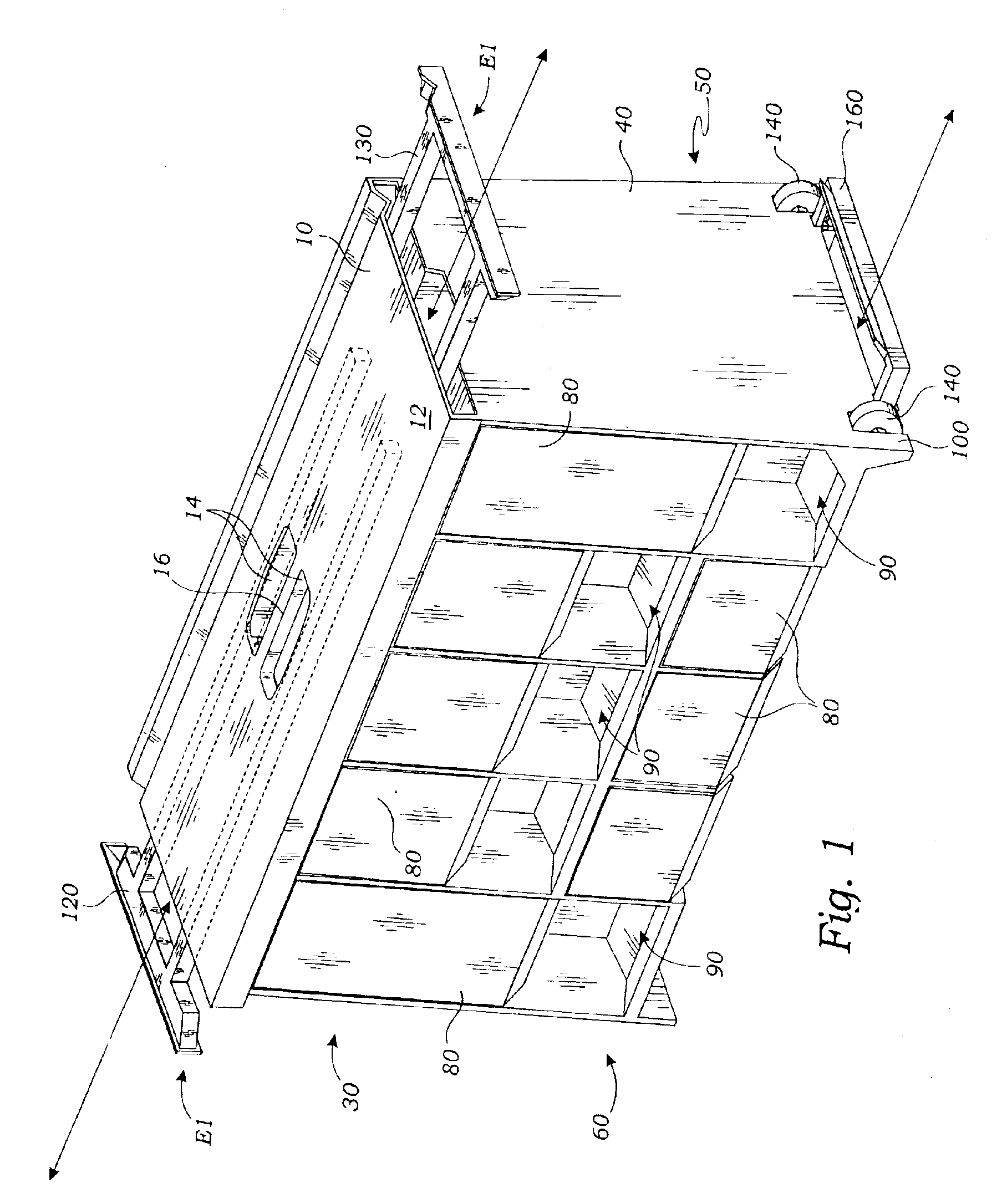
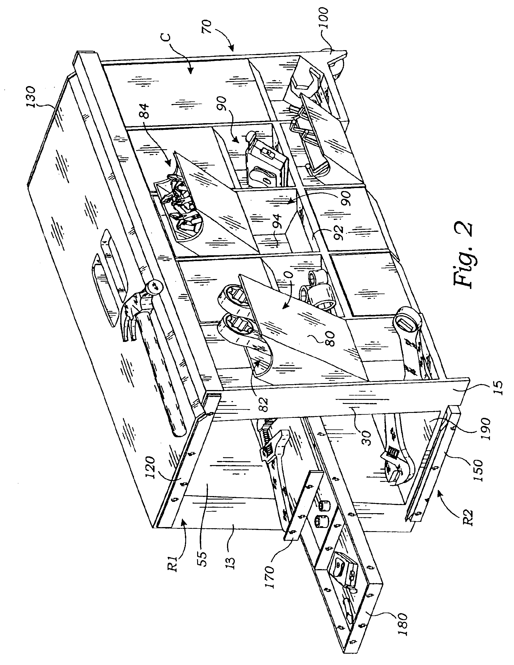
[0041]The present invention is a portable toolbox apparatus with several other key functions which will be described below. A top 10, bottom 20, front 30 and rear 40 forming a box structure 50 with opposing sides 60, 70 tilted off-vertical and made-up of a plurality of hinged drawers 80 having hinged drawer front faces, the front faces positioned on both of the opposing sides 60, 70 of the apparatus in mutually convergent planes. Fixed bins 90 are positioned in sides 60, 70 as well. These drawers 80 and bins 90, being accessible from the outside of the apparatus, function as a parts and tool crib to make the availability of items needed in working more convenient. The tilt of the sides provides for maintaining closure of the drawers 80 and movement of items to the rear of the drawers and bins to prevent loss,...


PUM


Abstract

The portable toolbox has a top, bottom, front and rear panels forming a box structure with opposing sides tilted off-vertical so as to converge upwardly. A plurality of hinged drawers and fixed bins are arranged on each side of the toolbox. The rear panel terminates at a pair of supporting feet for resting the apparatus on a supporting surface and a pair of wheels for moving the toolbox. By lifting the toolbox from its forward end, the toolbox moves from resting on its rear legs, to resting on its rear wheels. The top panel provides an upwardly facing work surface with a pair of hand holes separated by a hand grip for carrying the apparatus. A forward and a rearward sliding retractable work surface extender frames are positionable between a retracted position, secured within the box structure and an extended position directed outwardly from the box structure for resting a workpiece.

Description

RELATED APPLICATIONS[0001]This is a substitute application of a prior filed application having Ser. No. 09 / 909,203 and file date of Jul. 18, 2001.INCORPORATION BY REFERENCE[0002]Applicant(s) hereby incorporate herein by reference, any and all U.S. patents referred to in this application.BACKGROUND OF THE INVENTION[0003]1. Field of the Invention[0004]This invention relates generally to tool boxes and work benches and more particularly to a portable toolbox that functions as a work bench and stool.[0005]2. Description of Related Art[0006]The following art defines the present state of this field:[0007]Gale, U.S. D252,197 describes a combined tool cart and work table design.[0008]Walker, U.S. Pat. No. 1,027,945 describes a bin casing having a pivotal member comprising an angular flange; of a bin mounted in said casing and removably supported upon the angular ridge of said flange; and a vertical flange plate opposite to said pivotal flange arranged to limit the tilting motion of said bin...

Claims


Application Information

Patent Timeline
IPC IPC(8): B25H1/00B25H1/14B25H3/00B25H1/12B25H3/02B62B5/04B62B5/00
CPCB25H1/12B25H1/14B25H3/021B25H3/028B62B5/049
Inventor HAHN, RICHARD DUK WONG
Owner HAHN RICHARD DUK WONG
Learn More