Recirculating rolling element cartridge for linear motion bearing assembly

a technology of rolling element and linear motion, which is applied in the direction of bearings, bearings, shafts and bearings, etc., can solve the problems of difficult efficient manufacture, and the assembly of bearing assemblies, especially the assembly, is even more difficult to manufactur

Inactive Publication Date: 2005-09-06
THOMSON IND INC
View PDF7 Cites 12 Cited by
  • Summary
  • Abstract
  • Description
  • Claims
  • Application Information

AI Technical Summary

Problems solved by technology

This structure, however, is difficult to efficiently manufacture because of the complex molds required.
These bearing assemblies, particularly the assembly shown in the '992 patent, are even more difficult to manufacture because a plurality of ball tracks are being formed.
This technique is both time consuming and inefficient.
In addition to the problems associated with assembling and positioning the axial and inner guides, bearing assemblies making use of typical individual bearing plates tend to have alignment and positioning problems associated therewith.
If these bearing plates are not properly and securely positioned, the bearing assembly will not operate efficiently and may cause binding and / or misalignment of the rolling elements.
These designs for such linear bearing assemblies have some inherent drawbacks.
This arrangement does not make efficient usage of the space surrounding the rail and inhibits the placement of an optimum number of load-bearing paths for a given surface area.
Also, the ball turnaround structure creates a tight arc for reversal which limits the speed capacity and can result in stagnation of ball movement through the ball path.

Method used


Image

  • Recirculating rolling element cartridge for linear motion bearing assembly
  • Recirculating rolling element cartridge for linear motion bearing assembly
  • Recirculating rolling element cartridge for linear motion bearing assembly

Examples


Embodiment Construction

)

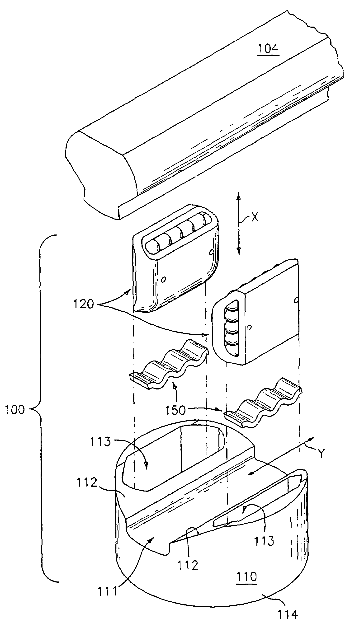
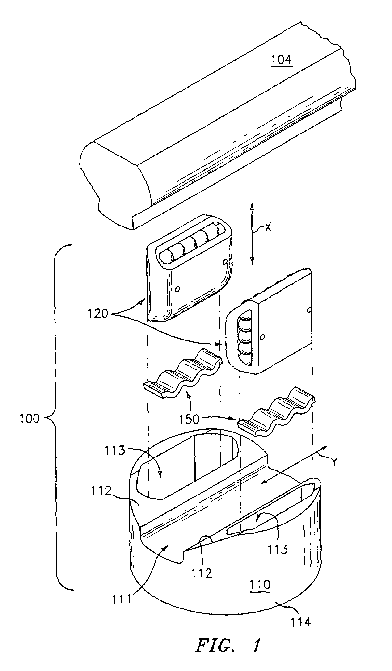
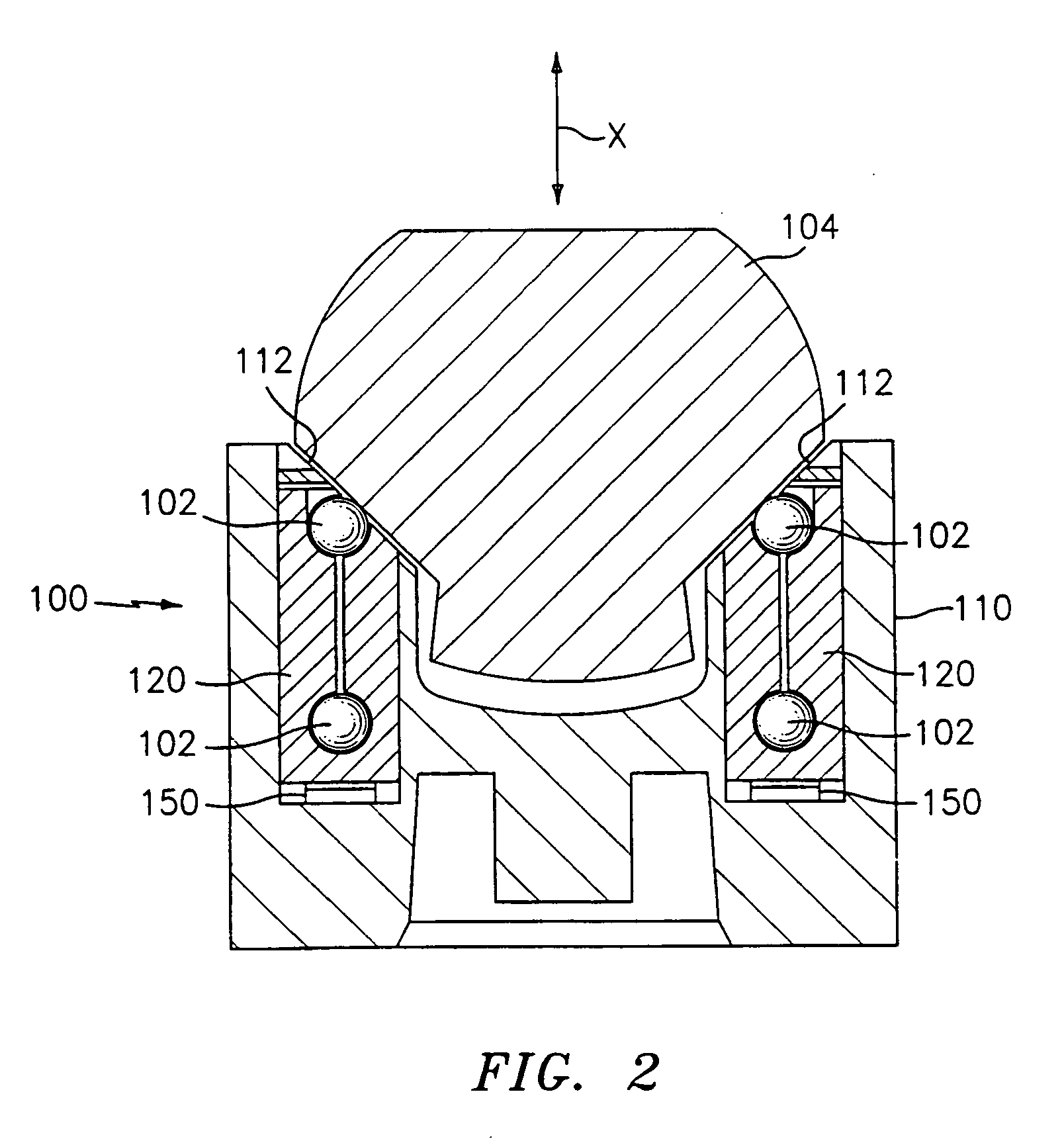
[0036]The bearing assembly of the present invention can be used, for example, in automotive vehicles for rack and pinion type steering apparatus, or in any other application wherein a moving shaft is supported on bearings. As used herein, the terms “vertical” and “horizontal” are used relative to each other. While the bearing assembly is described below in conjunction with the use of bearing balls, it should be noted that any type of rolling element is contemplated within the scope of this invention.

[0037]Referring now to FIGS. 1 and 2, a bearing assembly 100 is shown for supporting linearly movable shaft or rail or rack 104. Bearing assembly 100 includes housing block 110, bearing cartridges 120 and optional corrugated leaf springs 150. Bearing assembly 100 employs guided recirulation of rolling load bearing elements (e.g., bearing balls) to reduce frictional forces created with regard to two bodies moving relative to one another. The bearing assembly provides a smooth travel of m...


PUM


Abstract

A bearing assembly includes at least one and preferably two ball tracks each having a load-bearing portion, a return portion, and a turn-around portion, and a plurality of bearing balls, wherein the ball track is configured for the guided recirculation of the bearing balls. The bearing assembly includes a housing block with a channel at its distal end for receiving a movable shaft. The channel includes an elongated window aligned with each of the load-bearing portions of the tracks, the window allowing portions of the bearing balls to protrude therethrough to support the shaft. The bearing tracks define planes which can be oriented parallel to or perpendicular to the longitudinal axis of the housing block, or which together form an angled V-shaped configuration.

Description

[0001]This application claims benefir of provisional application No. 60 / 160,966, filed Oct. 22, 1999BACKGROUND[0002]1. Field of the Invention[0003]This invention relates to bearing assemblies, and more particularly to ball track bearing assemblies that reduce friction associated with movement of two bodies relative to each other.[0004]2. Description of the Related Art[0005]Bearing assemblies may be of the type which support a carriage or block for movement along a support member such as an elongated shaft, rail or spline to reduce friction associated with longitudinal or rotational motion. These bearing assemblies can be of the open or closed type.[0006]Bearing assemblies also contemplated by the present invention generally include an outer housing and a block dimensioned for insertion into the outer housing. The block defines a plurality of longitudinal planar faces each having at least one ball track in a loop configuration for containing and recirculating bearing balls. The ball ...

Claims


Application Information

Patent Timeline
Patent Type & Authority Patents(United States)
IPC IPC(8): F16C29/06F16H1/04
CPCF16C29/06Y10T74/1967
Inventor LYON, GREGORY S.NG, ALISONKIM, ERIC
Owner THOMSON IND INC
Why Eureka
Try Eureka