
Adjustable bed carriage

a bed carriage and adjustable technology, applied in the field of adjustable bed carriages, can solve the problems of relatively complex adjustment bed carriages, and relatively large number of components

Inactive Publication Date: 2005-09-13
SPAN MEDICAL PROD CANADA
View PDF46 Cites 23 Cited by
  • Summary
  • Abstract
  • Description
  • Claims
  • Application Information

AI Technical Summary

Benefits of technology

[0009]In another aspect, the invention provides an adjustable bed for use on a substantially planar floor. The adjustable bed includes a main bed frame, having a first end and a second end, and an adjustable bed carriage for supporting the main bed frame. The adjustable bed carriage has a first leg having an upper end slidably attached to the first end of the main bed frame and a second leg having an upper end pivotably attached to the second end of the main bed frame. Each of the first leg and the second leg are pivotably connected to each other at a central pivot located substantially at a midpoint of each leg to permit pivoting movement of each of the first leg and the second leg about the central pivot in the opposite directions. The pivoting movement of the legs moves the adjustable bed carriage between an extended condition and a retracted condition, moving the main bed frame relative to the plane of the floor.
[0012]In yet another aspect, the invention provides an adjustable bed for use on a substantially planar floor. The adjustable bed has a main frame for supporting a mattress, the main frame having a first end and a second end, a scissor leg assembly for supporting the main frame, and a motor mounted on the main frame and attached to the scissor leg assembly, for causing the scissor leg assembly to move between an extended condition, in which the main frame is in a fully raised position, and a retracted condition, in which the main frame is in a fully lowered position.

Problems solved by technology

However, scissor leg assemblies have not generally been used in adjustable bed carriages, and those that have suffer from some deficiencies.
However, the Bish et al. adjustable bed carriage is relatively complex, involving a relatively large number of components.

Method used


Image

  • Adjustable bed carriage
  • Adjustable bed carriage
  • Adjustable bed carriage

Examples


Embodiment Construction

)

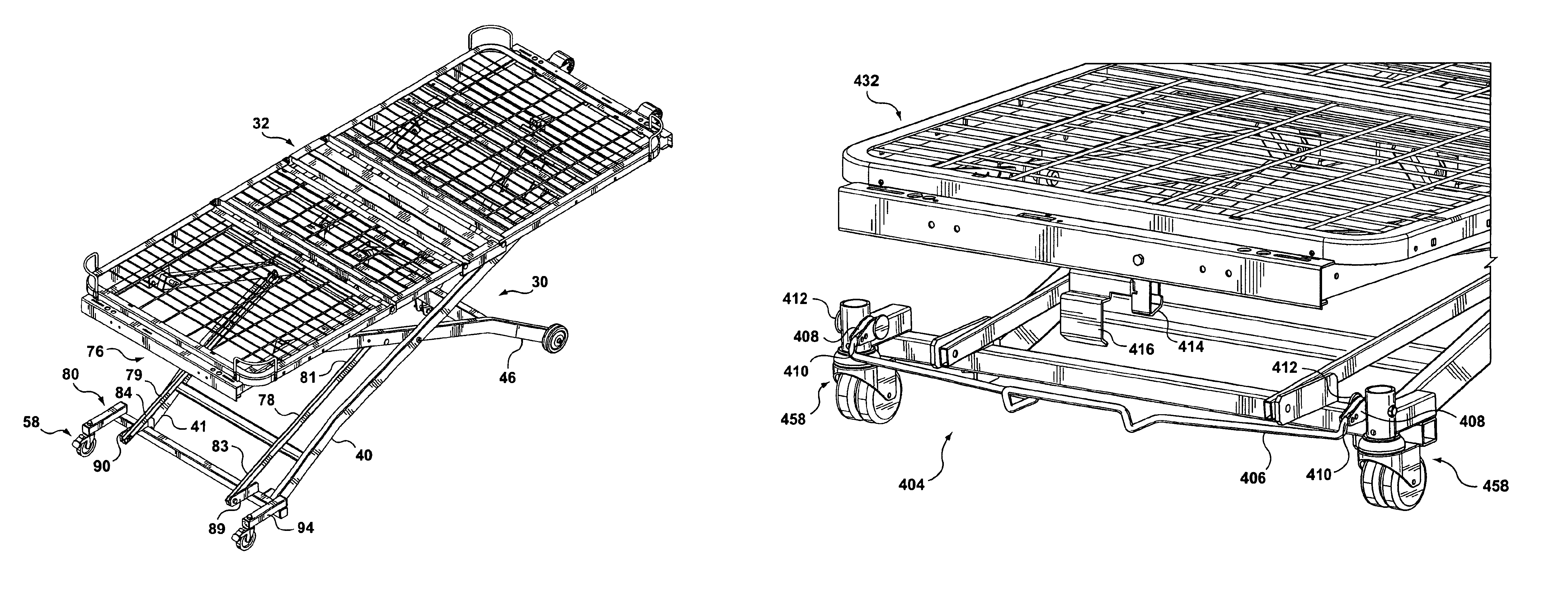
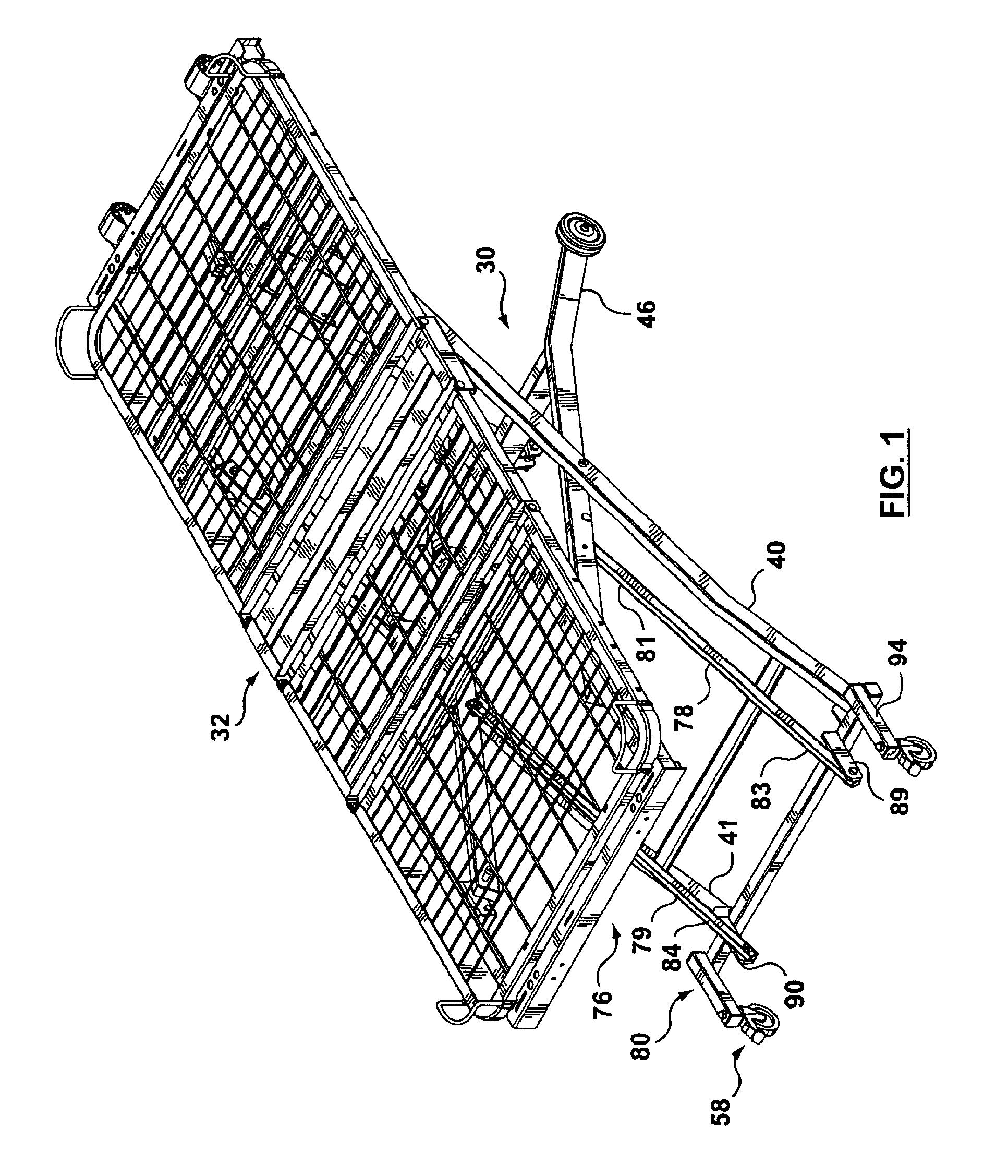
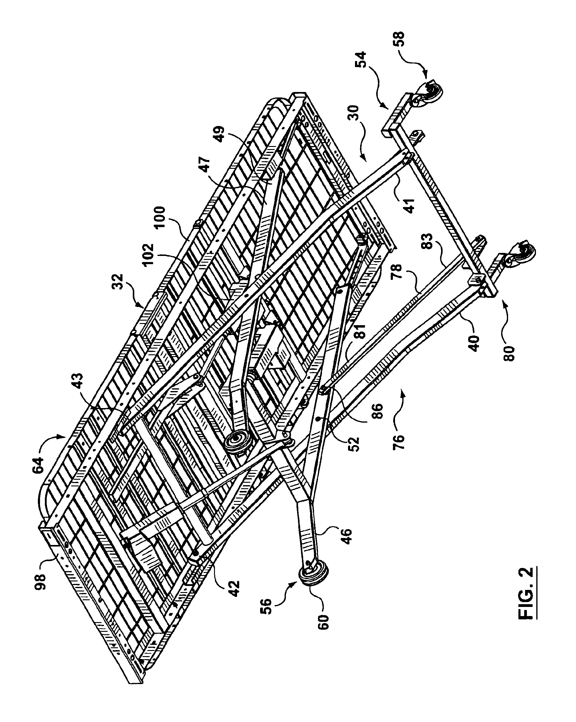
[0051]Reference is first made to FIGS. 1-8, 9A, 9B and 10 to describe a preferred embodiment of an adjustable bed carriage indicated generally by the numeral 30 in accordance with the invention. The adjustable bed carriage 30 is for supporting a main bed frame 32 above a substantially planar floor 34. In the preferred embodiment, the adjustable bed carriage 30 has first legs 40, 41 with upper ends 42, 43 respectively. Each upper end 42, 43 is slidably attached to a first end 44 of the main bed frame 32, as will be described. As can be seen in FIGS. 1 and 2, the adjustable bed carriage 30 also includes second legs 46, 47 with upper ends 48, 49 respectively, and each upper end 48, 49 is pivotably attached at a second end 50 of the main bed frame 32. In addition, each of the first legs 40, 41 and the second legs, 46, 47 are pivotably connected respectively at central pivots 52, 53 located substantially at the midpoints of the legs 40, 41 and 46, 47. The connections of the legs 40, 41 ...


PUM


Abstract

An adjustable bed carriage for supporting a main bed frame above a substantially planar floor. The adjustable bed carriage has a first leg with an upper end slidably attached to a first end of the main bed frame and a second leg with an upper end pivotably attached to a second end of the main bed frame. Each of the first leg and the second leg are pivotably connected to each other at a central pivot located substantially at a midpoint of each, to permit pivoting movement of each of the first leg and the second leg about the central pivot in opposite directions. The pivoting movement of the legs moves the adjustable bed carriage between a fully extended condition and a fully collapsed condition.

Description

[0001]This application claims the benefit of U.S. Provisional Application No. 60 / 421,077, filed Oct. 25, 2002.FIELD OF THE INVENTION[0002]This invention relates to an adjustable bed carriage for supporting a main bed frame.BACKGROUND OF THE INVENTION[0003]Known adjustable bed carriages are generally of three types. One type of adjustable bed carriage includes leg assemblies which are positioned at both ends of a main bed frame. An example of this type of known adjustable bed carriage is disclosed in U.S. Pat. No. 4,023,849 (Bethlen).[0004]A second general type includes extendable linkages at both ends of the main bed frame. For instance, such an adjustable bed carriage is disclosed in U.S. Pat. No. 4,097,939 (Peck et al.).[0005]The other well-known type of adjustable bed carriage includes a base supported by casters, wheels or feet on which legs (or linkages), are positioned, extending upwardly to the main bed frame. U.S. Pat. No. 3,462,772 (Morrison) discloses an example of this ge...

Claims


Application Information

Patent Timeline
Patent Type & Authority Patents(United States)
IPC IPC(8): A61G7/012A61G7/002B60B33/02B60B33/00A61G7/015A61G7/05A61G1/00A61G1/06A47C19/04
CPCA61G7/012B60B33/0007B60B33/0021B60B33/0039B60B33/0042B60B33/0049B60B33/0057B60B33/0063B60B33/0068B60B33/0073B60B33/0081B60B33/0092B60B33/021B60B33/026A61G7/015A61G2007/0528A61G7/0528
Inventor FREEBORN, BRIANHOUSE, TEDRUTHERFORD, GEOFF
Owner SPAN MEDICAL PROD CANADA
Learn More