Implantable device for covering and opening in a cranium

a mesh and cranial technology, applied in the field of cranial mesh, can solve the problems of overly rigid mesh with circular perforations, prone to cracking, and square perforation mesh design in u.s. pat. no. 5,346,492 has a drawback though, and does not always provide sufficient attachment strength

Inactive Publication Date: 2005-09-13
INTEGRA SIGNATURE TECH +1
View PDF3 Cites 45 Cited by
  • Summary
  • Abstract
  • Description
  • Claims
  • Application Information

AI Technical Summary

Problems solved by technology

Clinical testing has shown that such a mesh having circular perforations is overly rigid and subject to cracking.
The square perforation design of the mesh in U.S. Pat. No.

Method used


Image

  • Implantable device for covering and opening in a cranium
  • Implantable device for covering and opening in a cranium
  • Implantable device for covering and opening in a cranium

Examples


Embodiment Construction

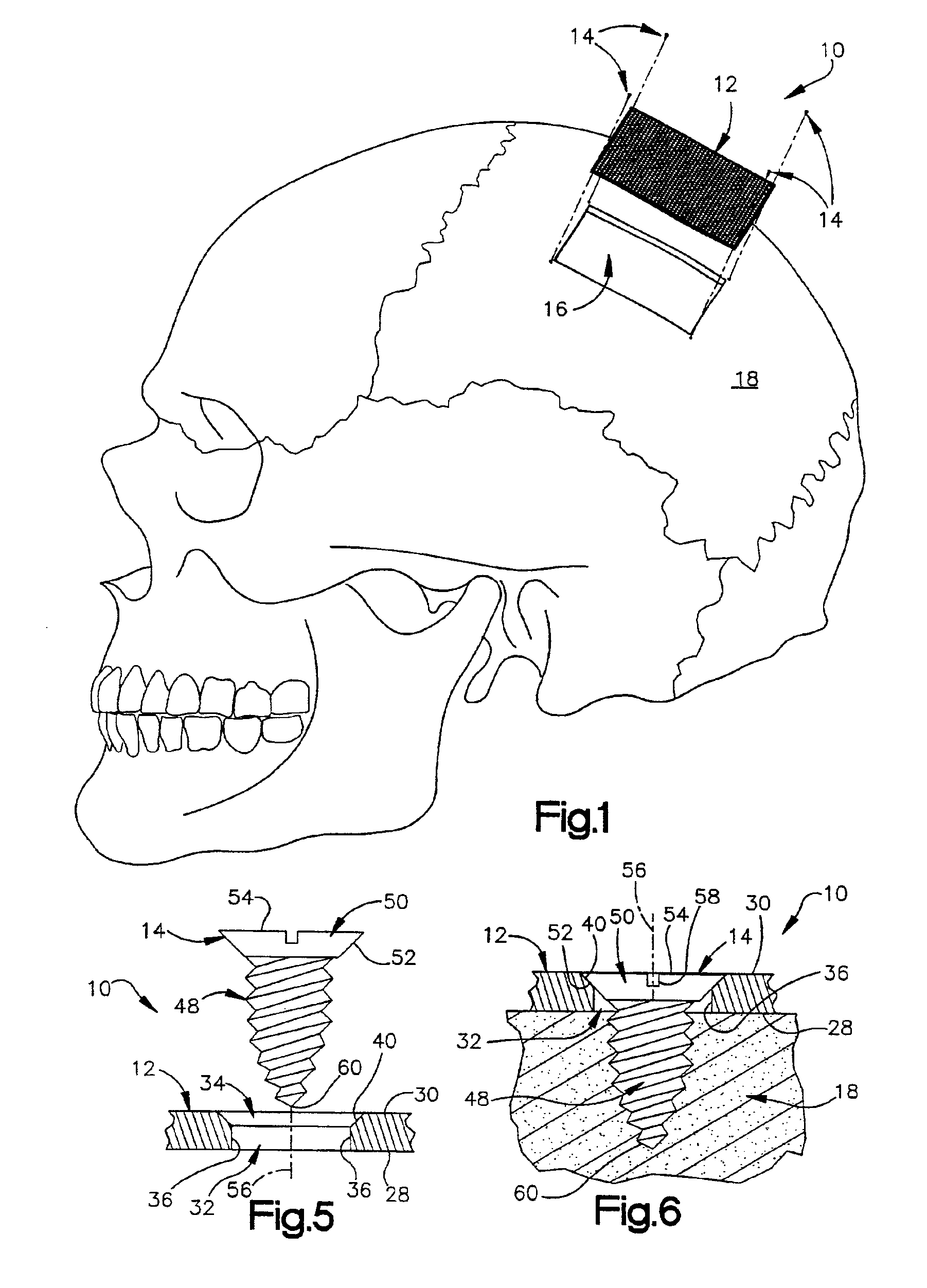
[0014]An apparatus 10 constructed in accordance with the present invention is illustrated in FIG. 1. The apparatus 10 includes a cranial mesh. FIG. 1 illustrates the apparatus 10 in spaced relation to an opening 16 in a cranium 18. The cranial mesh 12 covers the opening 16 in the cranium 18 and is fixedly attached to the cranium with a plurality of bone screws 14, four of which are illustrated in FIG. 1.

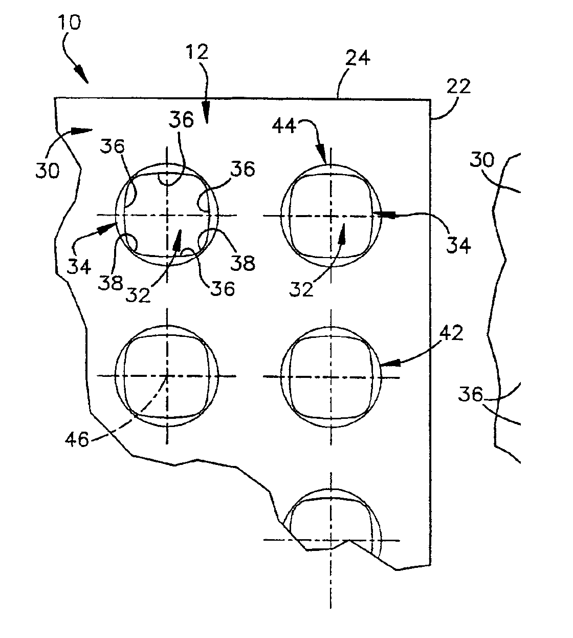
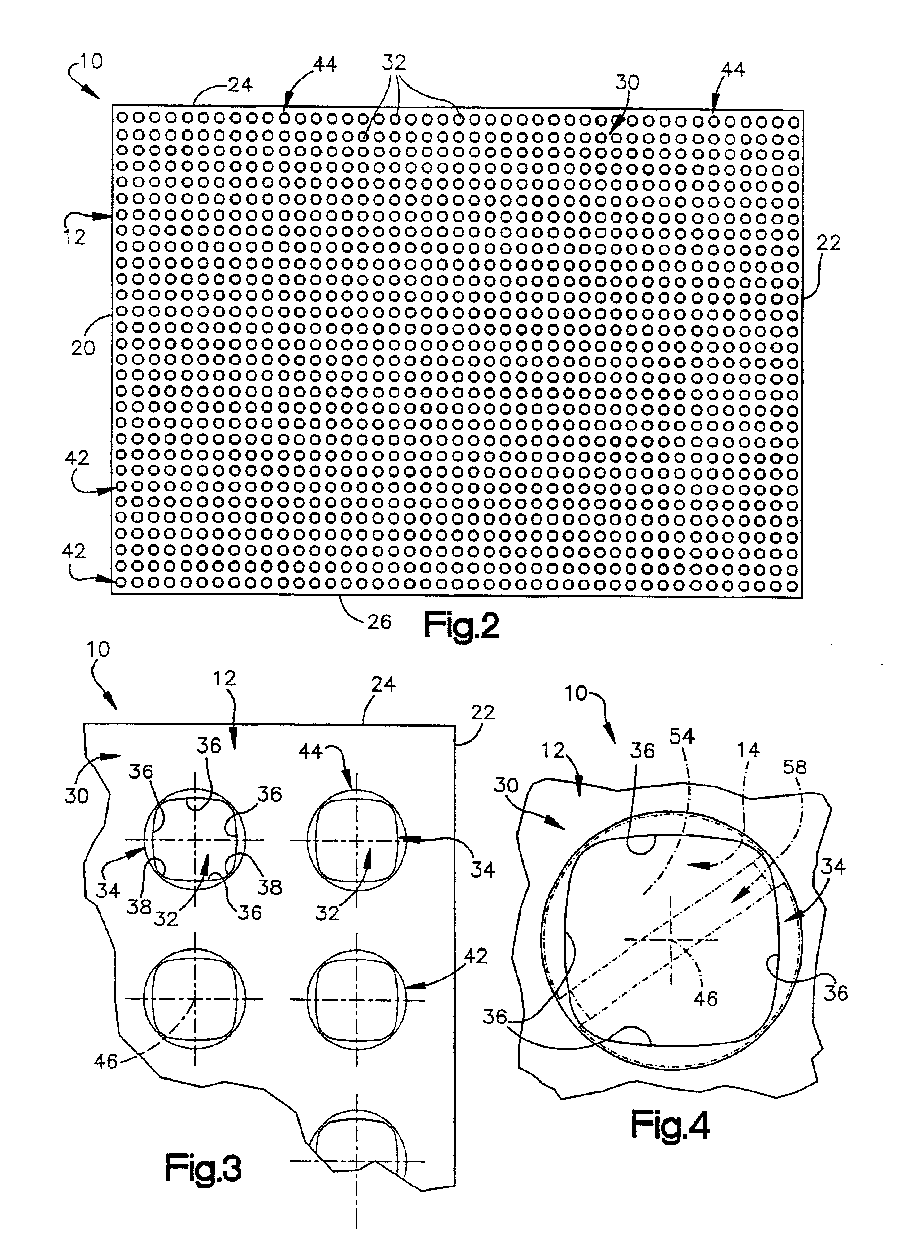
[0015]FIG. 2 illustrates a plan view of the cranial mesh 12. In accordance with one embodiment of the invention, the cranial mesh 12 is a rectangular plate having first and second short side walls 20 and 22, respectively, and first and second long side walls 24 and 26, respectively. The distance between the first and second short side walls 20 and 22 defines a length of the cranial mesh 12 and the distance between the first and second long side walls 24 and 26 defines a width of the cranial mesh. The length and the width of the cranial mesh are chosen to completely cover the opening ...


PUM


Abstract

An apparatus (10) for attachment to bone (18) comprises a plate (12) having a lower surface (28) for abutting against the bone (18) and an upper surface (30) opposite the lower surface (28). The plate (12) further includes a plurality of through-holes (32) extending between the lower and upper surfaces (28 and 30). Each through-hole (32) has an associated countersink (34). Each through-hole (32) defines a substantially square opening in the lower surface (28) of the plate (12) and each associated countersink (34) defines a circular opening in the upper surface (30) of the plate (12).

Description

TECHNICAL FIELD[0001]The present invention relates to an implantable surgical mesh for attachment to bone. More particularly, the present invention relates to a cranial mesh for attachment to the cranium.BACKGROUND OF THE INVENTION[0002]A known surgical mesh for cranial applications is disclosed in U.S. Pat. No. 5,346,492. The known mesh includes a plurality of chamfered, square perforations, each for receiving a screw. The square configuration of the perforations makes the mesh more flexible than if the perforations were true circles. Clinical testing has shown that such a mesh having circular perforations is overly rigid and subject to cracking. By rounding the corners of generally square-shaped perforations, a mesh with sufficient flexibility and resistance to cracking is produced.[0003]The square perforation design of the mesh in U.S. Pat. No. 5,346,492 has a drawback though. When a screw is received through a respective square perforation, only point contact is made between a h...

Claims


Application Information

Patent Timeline
IPC IPC(8): A61B17/68A61B17/80A61F2/28A61B17/86A61F2/00A61F2/30
CPCA61B17/8085A61F2/2846A61F2/2875A61B17/8052A61B17/8061A61B17/8605A61F2002/285A61F2002/30112A61F2002/30113A61F2002/30153A61F2002/30154A61F2002/30785A61F2002/30787A61F2002/30794A61F2230/0004A61F2230/0006A61F2230/0019A61F2230/0021A61F2310/00023Y10S606/903A61F2002/3079
Inventor GAMBALE, MICHAEL A.
Owner INTEGRA SIGNATURE TECH
Why Eureka
Try Eureka