Walk in apparatus for vehicle seat

Inactive Publication Date: 2005-09-20
AISIN SEIKI KK
View PDF12 Cites 24 Cited by
  • Summary
  • Abstract
  • Description
  • Claims
  • Application Information

AI Technical Summary

Benefits of technology

[0005]The invention involves a walk-in apparatus of a vehicle seat which comprises a slide rail mechanism including an upper rail which is assembled to a vehicle seat side and a lower rail which is engaged slidably with the upper rail and assembled to a vehicle floor side, the slide rail mechanism supporting the vehicle seat for allowing a position of the vehicle seat to be adjusted relative to the vehicle floor in vehicle longitudinal direction, a lock plate assembled to the upper rail for locking the slide movement of the upper rail on the lower rail, a release lever which is assembled to the upper rail for releasing the locking of the slide movement of the upper rail on the lower rail by the lock plate and adapted to engage with the lock plate, a supporting lever which is assembled to the upper rail and adapted to engage with the release lever, a reclining plate which rotates in conjunction with a seat back when the seat back is rotated equal to or more than a predetermined angle in forward direction by an actuation of a reclining arm mechan

Problems solved by technology

As a result, the walk-in ap

Method used


Image

  • Walk in apparatus for vehicle seat
  • Walk in apparatus for vehicle seat
  • Walk in apparatus for vehicle seat

Examples


Embodiment Construction

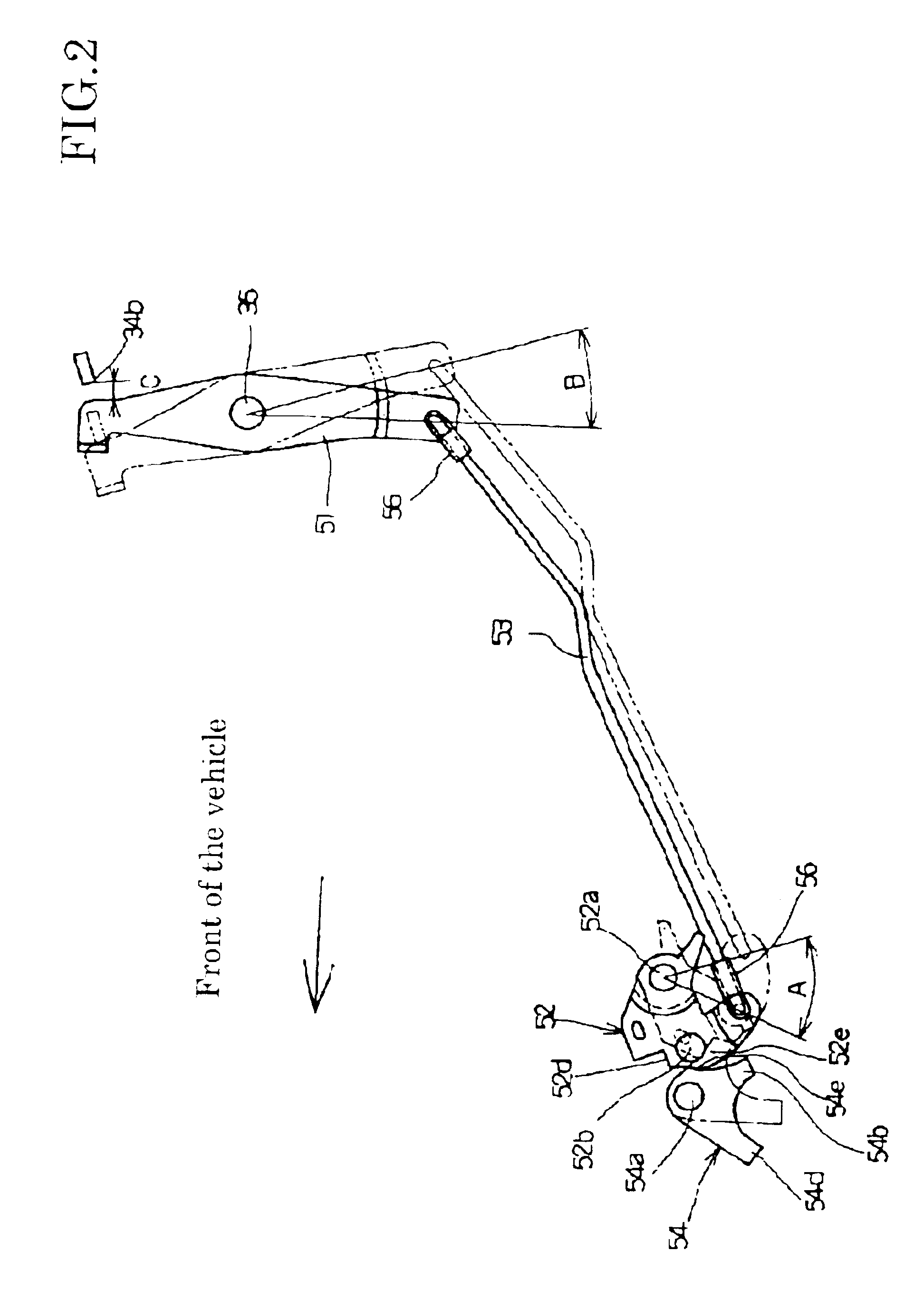
[0013]Referring now to an embodiment of the walk-in apparatus for the vehicle of the present invention with reference to the attached drawings, FIG. 1 through FIG. 6.

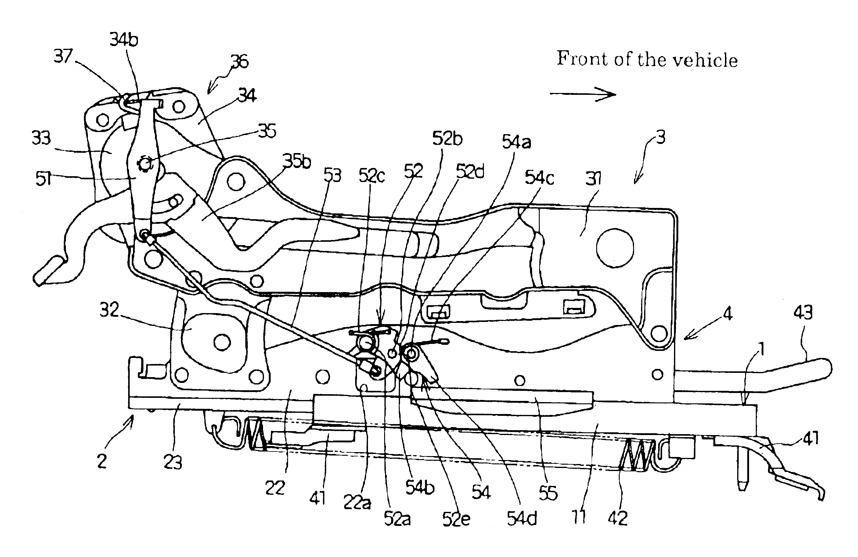
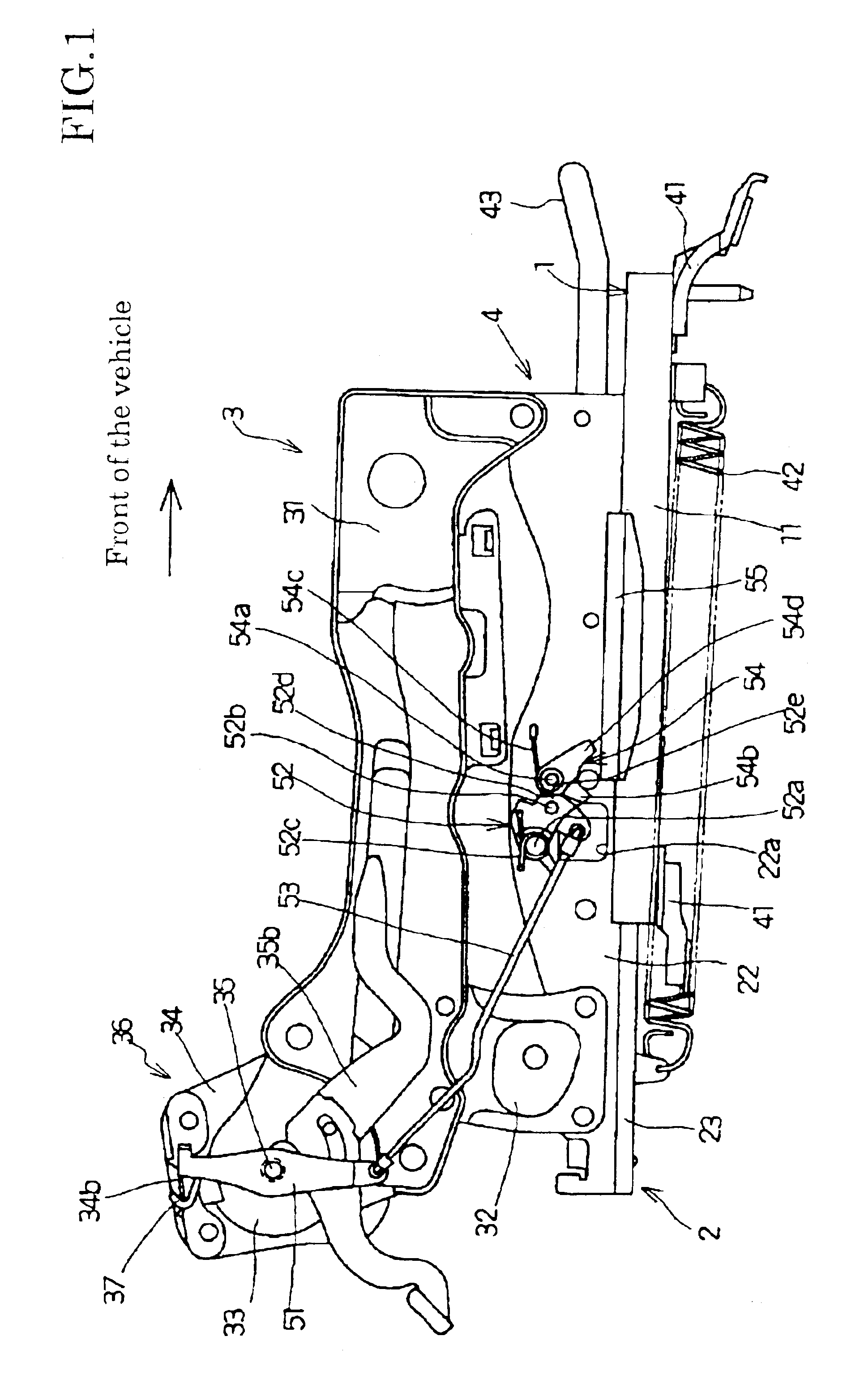
[0014]As shown in FIG. 1, a slide rail mechanism 4 in accordance with the invention is attached to the both right and left of the vehicle seat and bears a pair of lower rails 1. The lower rails 1 are arranged parallel to each other and secured to the vehicle floor (not shown) by a bracket 41. The lower rail 1 is elongated in vehicle longitudinal direction and includes side walls 11 and a base portion 12. The base portion 12 is provided between both side walls 11 for connecting each other, so that the lower rail 1 has an approximately U-shaped form from its cross sectional view as shown in FIG. 3 through FIG. 5. Engaging flange walls 13 are formed on the lower rail 1, which continuously extend from the top edges of the both side walls 11 and bend inwardly facing each other with a predetermined clearance.

[0015]Upper rail ...


PUM


Abstract

A walk-in apparatus of a vehicle seat slide includes an upper rail and a lower rail, a lock plate for locking the upper rail position on the lower rail, a release lever engaging with the lock plate for releasing the locking, a supporting lever engaging the release lever, a reclining plate rotating when the seat back rotates more than a predetermined forward angle, a memory plate on the lower rail within a predetermined range, a first supporting portion on the supporting lever for holding the release lever at a first position where the lock plate unlocks when the supporting lever is out of the memory plate range and a second supporting portion provided on the supporting lever for holding the release lever at a second position and waiting for the upper rail to be locked when the reclining plate disengages with the seat back.

Description

[0001]This application is based on and claims priority under 35 U.S.C. § 119 with respect to Japanese Application No. 2002-285352 filed on Sep. 30, 2002, the entire content of which is incorporated herein by reference.FIELD OF THE INVENTION[0002]This invention generally relates to a walk-in apparatus for a vehicle seat. More particularly, the present invention pertains to the walk-in apparatus for the vehicle seat, which provides a forward slide movement of the vehicle seat relative to a vehicle floor in conjunction with a forward reclining movement of a seat back of the vehicle seat relative to a seat cushion.BACKGROUND OF THE INVENTION[0003]A known walk-in apparatus is disclosed, for example, in the U.S. Pat. No. 6,341,819 as a seat slide device for a vehicle. The walk-in apparatus has been known comprising a slide rail mechanism which slidably supports the vehicle seat in longitudinal direction relative to the vehicle floor, a lock plate which locks the slide rail mechanism and r...

Claims


Application Information

Patent Timeline
IPC IPC(8): B60N2/12B60N2/08
CPCB60N2/12
Inventor KOJIMA, YASUHIRO
Owner AISIN SEIKI KK
Why Eureka
Try Eureka