Cradle for digital camera

a digital camera and cradle technology, applied in the field of cradles, can solve the problem that the connecting cord cannot be connected directly to such connecting terminals, and achieve the effect of preventing a setting deficiency of the digital camera

Inactive Publication Date: 2005-09-27
FUJIFILM CORP +1
View PDF8 Cites 57 Cited by
  • Summary
  • Abstract
  • Description
  • Claims
  • Application Information

AI Technical Summary

Benefits of technology

[0007]The present invention has been accomplished in view of the above-described situation. Accordingly, an object of the present invention is to provide a cradle for a digital camera that is capable, when a digital camera is set in the cradle, of preventing redundant connection of connecting cords to those of a plurality of connecting terminals formed in the digital camera that are of kinds that are also connected to connecting terminals provided at the cradle.
[0011]Consequently, further according to the first aspect of the present invention, it is possible to prevent redundant connection of a charging cord and / or external device connecting cord to the charging terminal and / or external device connecting terminal of the digital camera.
[0013]Consequently, further according to the second aspect of the present invention, it is possible to prevent redundant connection of a personal computer connecting cord to the personal computer connecting terminal of the digital camera.
[0015]Consequently, further according to the first to third aspects of the present invention, since a predetermined position of the shield is aligned with the set-state comfirmation means formed on the side of the digital camera when the digital camera is set in the retainer in the digital camera cradle, it is possible to confirm that the digital camera is completely set in the retainer. As a result, it is possible to prevent a setting deficiency of the digital camera in the digital camera cradle.

Problems solved by technology

Consequently, when the digital camera is set in the retainer in the digital camera cradle, since the shield formed at the retainer shields those of the plurality of connecting terminals formed in the digital camera that are of kinds that are also connected to the connecting terminals provided at the cradle, connecting cords cannot be connected directly to such connecting terminals.

Method used


Image

  • Cradle for digital camera
  • Cradle for digital camera
  • Cradle for digital camera

Examples


Embodiment Construction

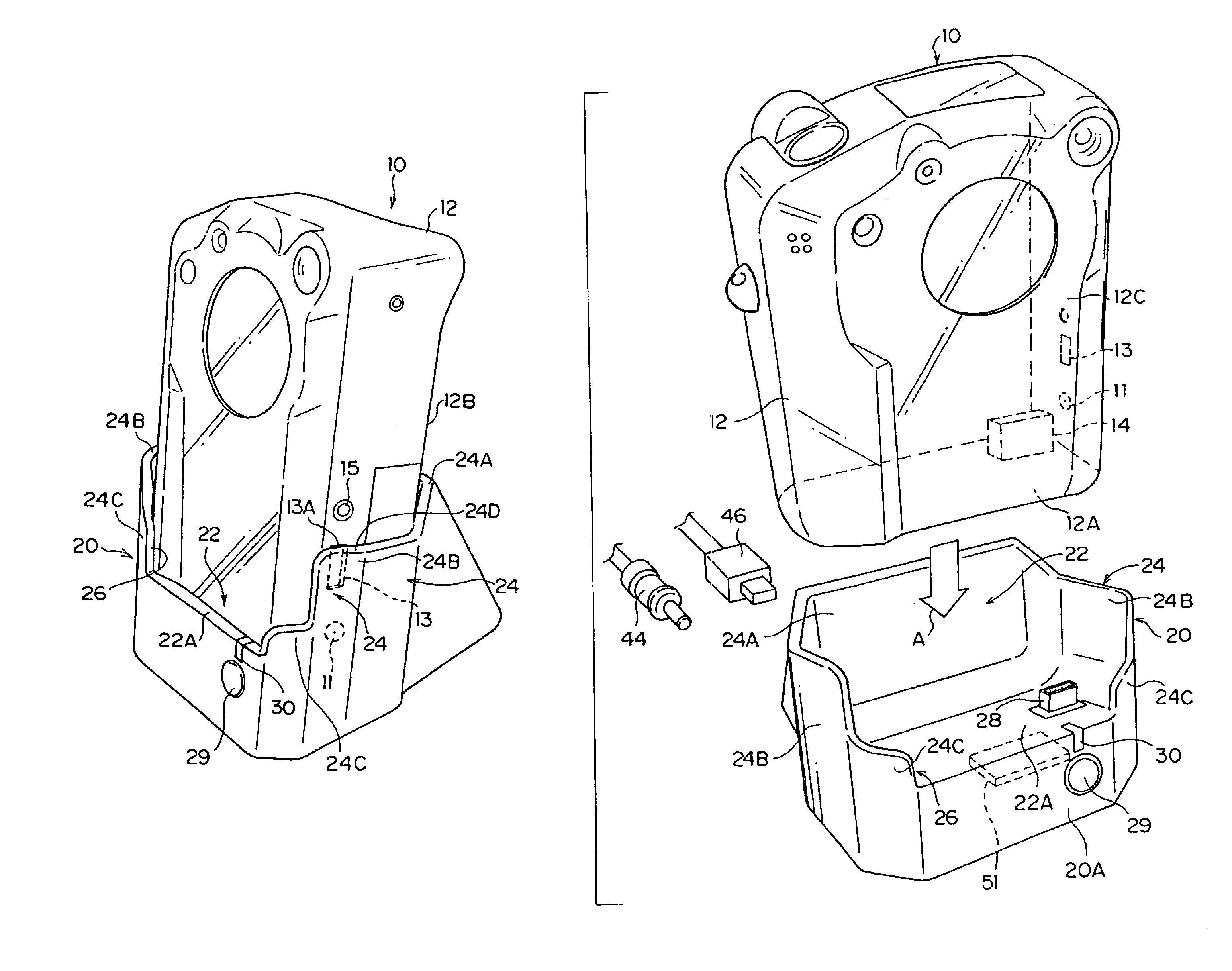
[0025]A digital camera cradle according to a first embodiment of the present invention will be described hereinafter with reference to FIGS. 1 to 5 and 9.

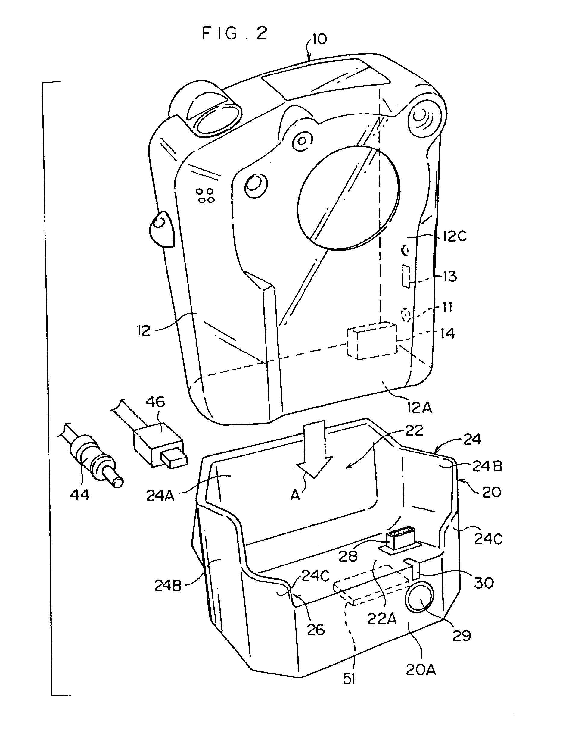
[0026]As shown in FIG. 2, a composite terminal 14 configured by integrating with each other a charging terminal and a USB terminal that serves as a personal computer connecting terminal is formed at a lower surface 12A of a casing 12 of a digital camera 10. The digital camera 10 can be inserted from above down into a retainer 22 in a digital camera cradle 20 (in a direction indicated by an arrow A in FIG. 2).

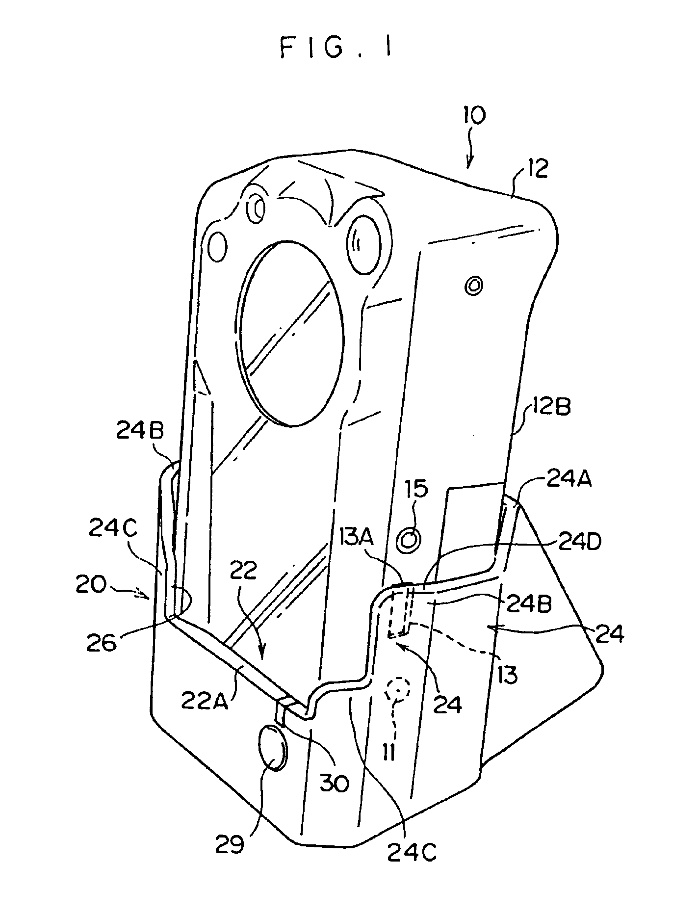
[0027]As shown in FIG. 1, a charging terminal 11 and a USB terminal 13, which serves as a personal computer connecting terminal or an external device connecting terminal, are formed at a lower portion of a side surface 12B of the casing 12 of the digital camera 10. The charging terminal 11 and the USB terminal 13 are used when the digital camera 10 is not set in the digital camera cradle 20. Furthermore, an AV (audio / video) ter...


PUM


Abstract

A cradle for a digital camera. When a digital camera is set in a retainer of the cradle, side portions of a wall formed at the retainer are disposed to shield a charging terminal and a USB terminal formed at a lower portion of a side surface of a casing of the digital camera. Thus, a charging cord and a USB cord cannot be connected directly to the charging terminal and the USB terminal when the digital camera has been set in the digital camera cradle. That is, when the digital camera is set in the cradle, it is possible to prevent redundant connection of connecting cords to any ones of a plurality of connecting terminals formed in the digital camera that are of kinds the same as other connecting terminals of the digital camera, which others are connected to connecting terminals provided at the cradle.

Description

BACKGROUND OF THE INVENTION[0001]1. Field of the Invention[0002]The present invention relates to a cradle for retaining therein a digital camera provided with a plurality of connecting terminals.[0003]2. Description of the Related Art[0004]As shown in FIG. 8, there has been conventionally a digital camera 200 provided with a plurality of connecting terminals such as a charging (power source) terminal 204 and a USB terminal 206 serving as an external device connecting terminal at the lower portion of a side surface 202A of a casing 202.[0005]However, in the above-described configuration, as shown in FIG. 8, the charging terminal 204 and the USB terminal 206 formed in the digital camera 200 may be exposed to the outside in the state in which the digital camera 200 is set in a digital camera cradle 210. In the digital camera cradle 210, a charging terminal connector and a USB terminal connector, neither shown, are generally formed at a retaining surface 210A for retaining the digital c...

Claims


Application Information

Patent Timeline
Patent Type & Authority Patents(United States)
IPC IPC(8): H04N5/232H02J7/00G03B17/56H04N1/00H04N5/225H04N101/00
CPCH02J7/0044H04N1/00127H04N5/232H04N2201/0058H04N23/50H04N23/00
Inventor SOUMI, MITSUOKANAMORI, SHINO
Owner FUJIFILM CORP
Why Eureka
Try Eureka