

Electrical plug connector with cable manager
- Summary
- Abstract
- Description
- Claims
- Application Information
AI Technical Summary
Benefits of technology
Problems solved by technology
Method used
Image

Examples
Embodiment Construction
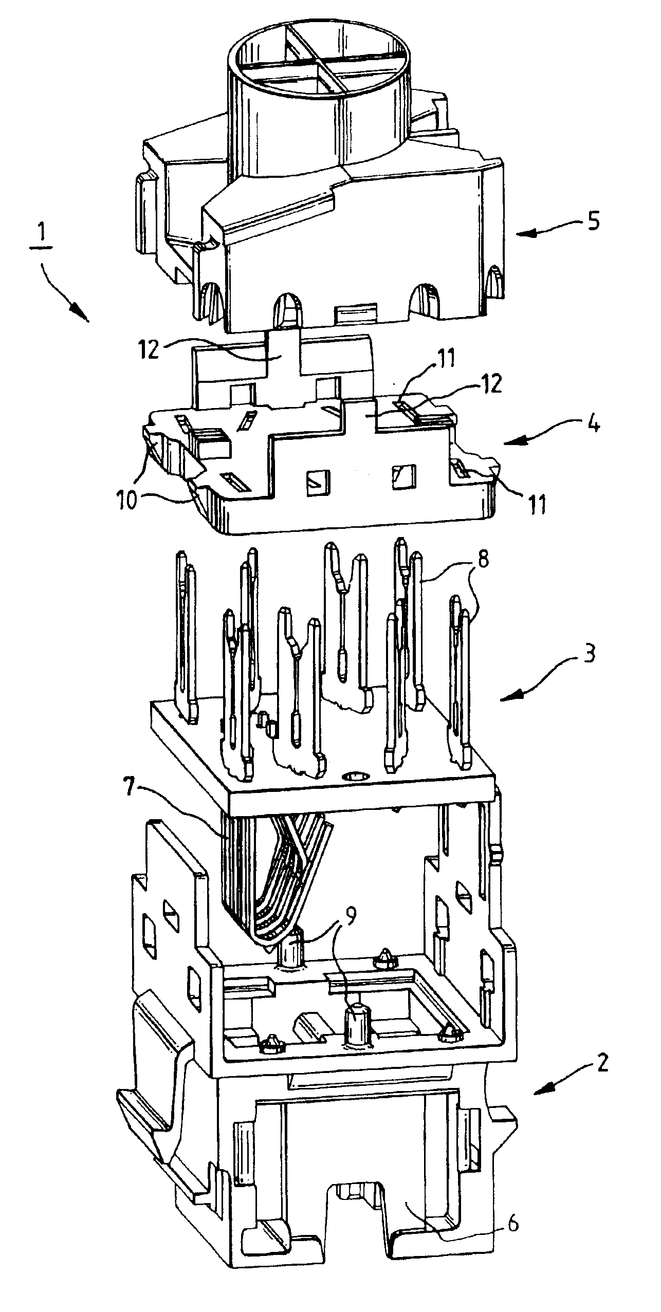
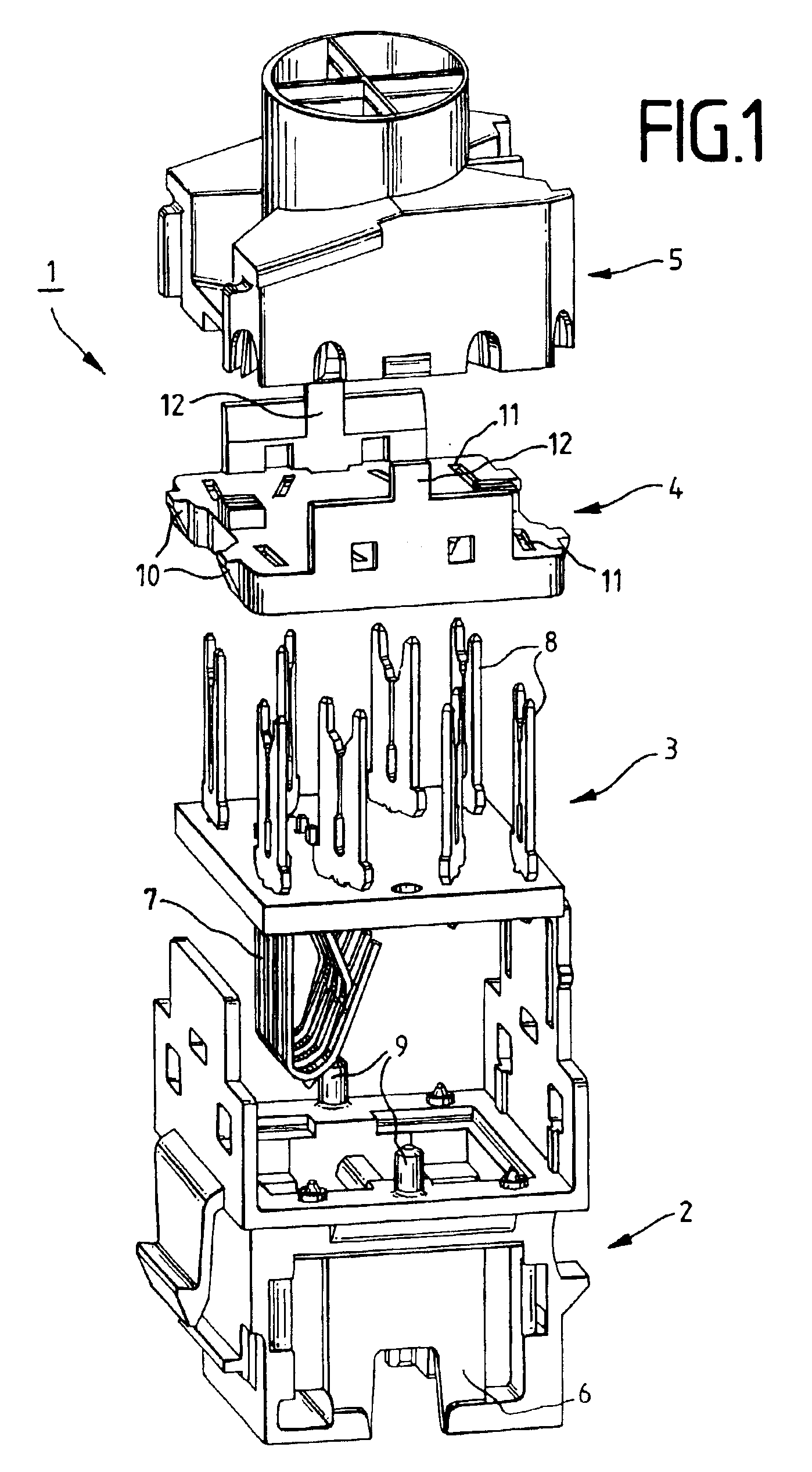
[0029]Referring to the drawings in particular, FIG. 1 shows an exploded illustration of a plug connector 1. The plug connector 1 comprises a plug connector housing 2, a printed circuit board 3, a hold-down device 4 and a cable manager 5. The plug connector housing 2 in the illustrated examples is in the form of a socket housing with various latching and insertion means. The plug connector housing 2 is designated with a shielding plate 6 on the side surface. The printed circuit board 3 is fitted with a first set of contacts 7 on its front face and with a second set of insulation-displacement contacts 8 on its rear surface. One contact 7 in the first set is in each case connected to one contact 8 in the second set. The printed circuit board 3 is then inserted in to the plug connector housing 2. In the process, cylindrical pins 9 on the plug connector housing 2 pass through holes in the printed circuit board 3, so that the plug connector housing 2 and printed circuit boar 3 can be adju...
PUM
 Abstract
Description
Claims
Application Information