Laser marking system

a laser marking and marking system technology, applied in the field of laser marking devices and systems, can solve the problems of consuming much valuable floor space/area, escaping laser light, damaging other surfaces, etc., and achieves the effects of less integration and assembly time, minimal footprint area, and low overall cos

Active Publication Date: 2009-07-16
MECCO PARTNERS
View PDF9 Cites 6 Cited by
  • Summary
  • Abstract
  • Description
  • Claims
  • Application Information

AI Technical Summary

Benefits of technology

[0015]In terms of function and capability, the novel device of the present invention contains the marking laser light within a confined marking chamber. In a preferred embodiment, it can meet or exceed a CDRH Class 1 rating for laser safety for production laser marking / engraving. And it accomplishes this in a minimal footprint area, with lower overall cost, less integration and assembly time for the end user, and with a system and device that is easy to integrate into existing automation, e.g. in to existing assembly lines or plants.
[0016]In terms of design, the present invention utilizes a unique combination of sensing devices and an enclosure system which includes at least one vacuum chamber and at least one marking chamber, wherein at least a portion of at least one surface of the part being marked forms at least one side of the enclosure. The laser marking system and device of the present invention, among other advantages: 1) eliminates the possibility that a damaged part, improperly located part or a part with an undesirable hole or other deformation will be marked, thus also eliminating undesirable exposure of the surroundings to stray laser radiation; 2) eliminates the possibility of accidental marking of materials of the type not intended to be marked, for example, if metallic parts were intended to be marked, non-metallic parts such as glass or human body parts will not be marked, conversely if the material intended to be marked is plastic, metal surfaces will not be marked, etc.; and 3) eliminates the possibility that a part not fully seated and sealed is marked, thus again, also eliminating undesirable exposure of the surroundings to stray laser radiation.

Problems solved by technology

One challenge with such devices and / or systems is to know when the part to be marked is properly positioned before the marking head, and that the part or other item to be marked is not deformed or otherwise compromised.
Another challenge is preventing the laser light from escaping a confined marking space.
This is undesirable because it can lead to marking surfaces that were not intended to be marked and / or to damaging other surfaces with such stray light.
Meeting this standard often consumed much valuable floor space / area and can be costly component of the device.
And attempts to meet this standard while minimizing floor space have lead to systems that are arguably in some instances not safe for production environments.
For example, some systems may utilize only 2 sensors to detect the item or device to be marked and do not verify part integrity, light seal and / or material presence.
Attempts have been made to address some of these problems, but the resulting systems and devices have been either complex and unwieldy or very costly to manufacture, and in some cases, such devices and / or systems have proven to be unreliable.
Reliability has been a particularly difficult challenge where the laser marking device is utilized in a manufacturing or similar environment, where the demands on the device can be very harsh indeed.

Method used


Image

  • Laser marking system
  • Laser marking system
  • Laser marking system

Examples


example 1

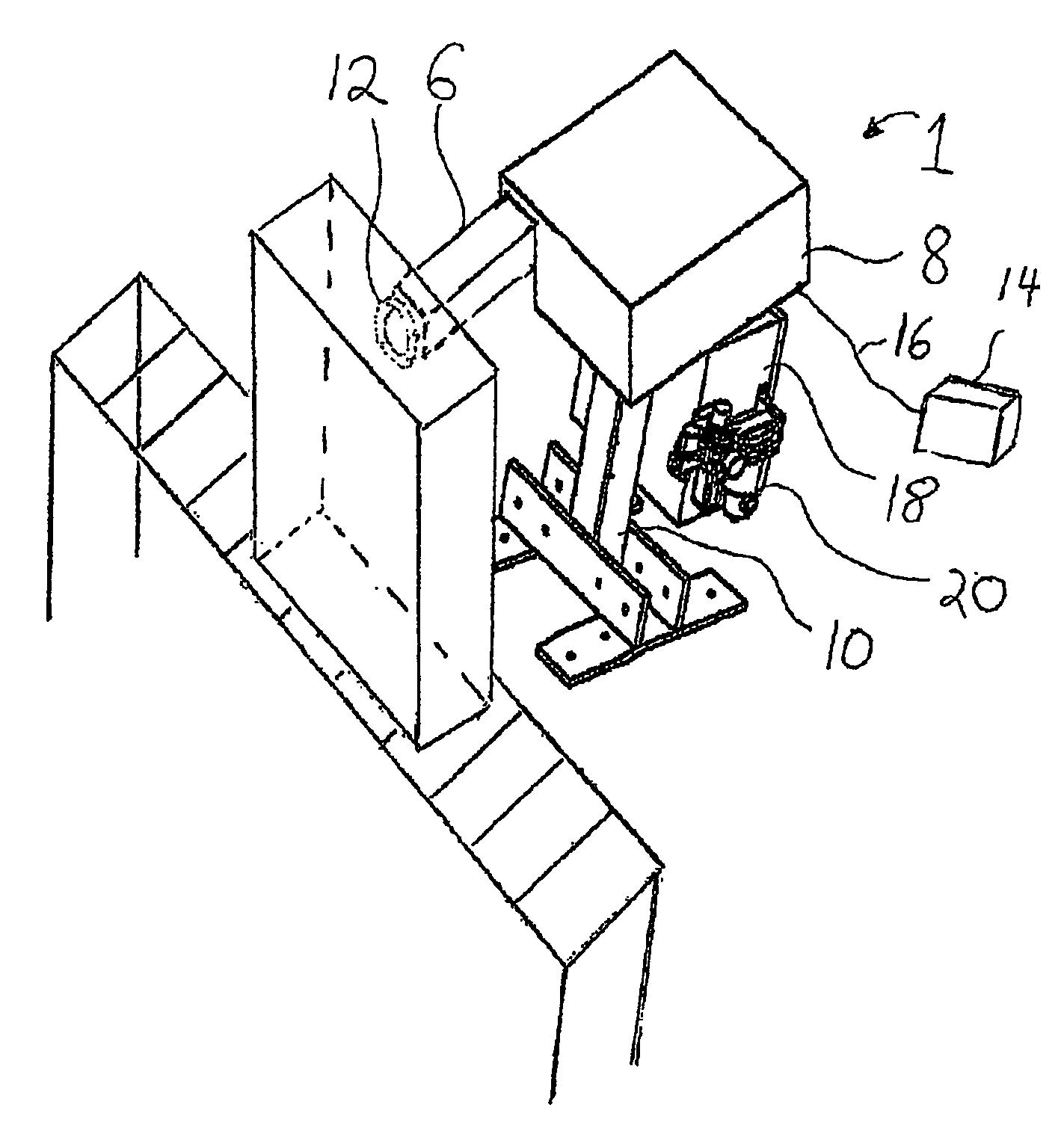
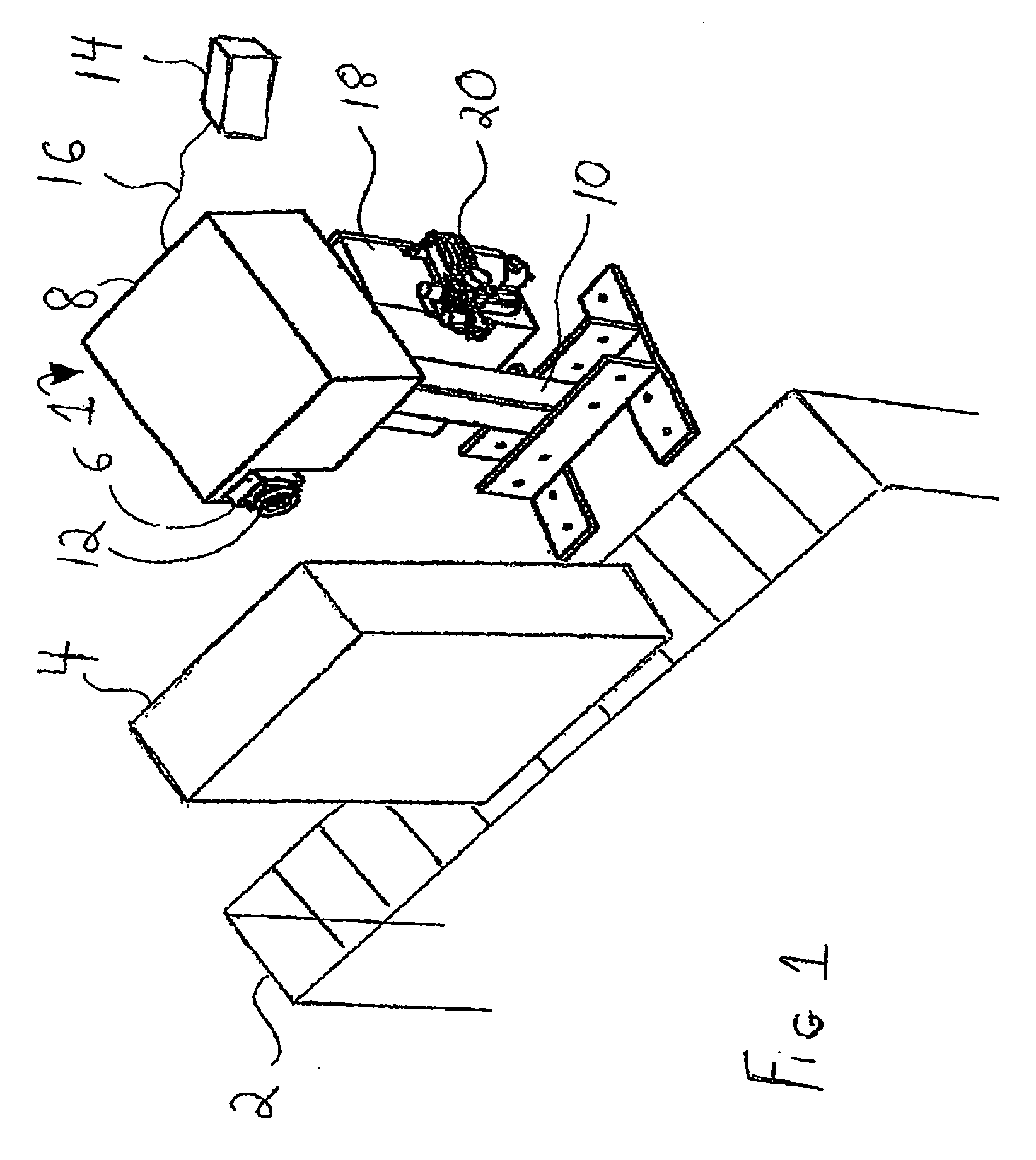
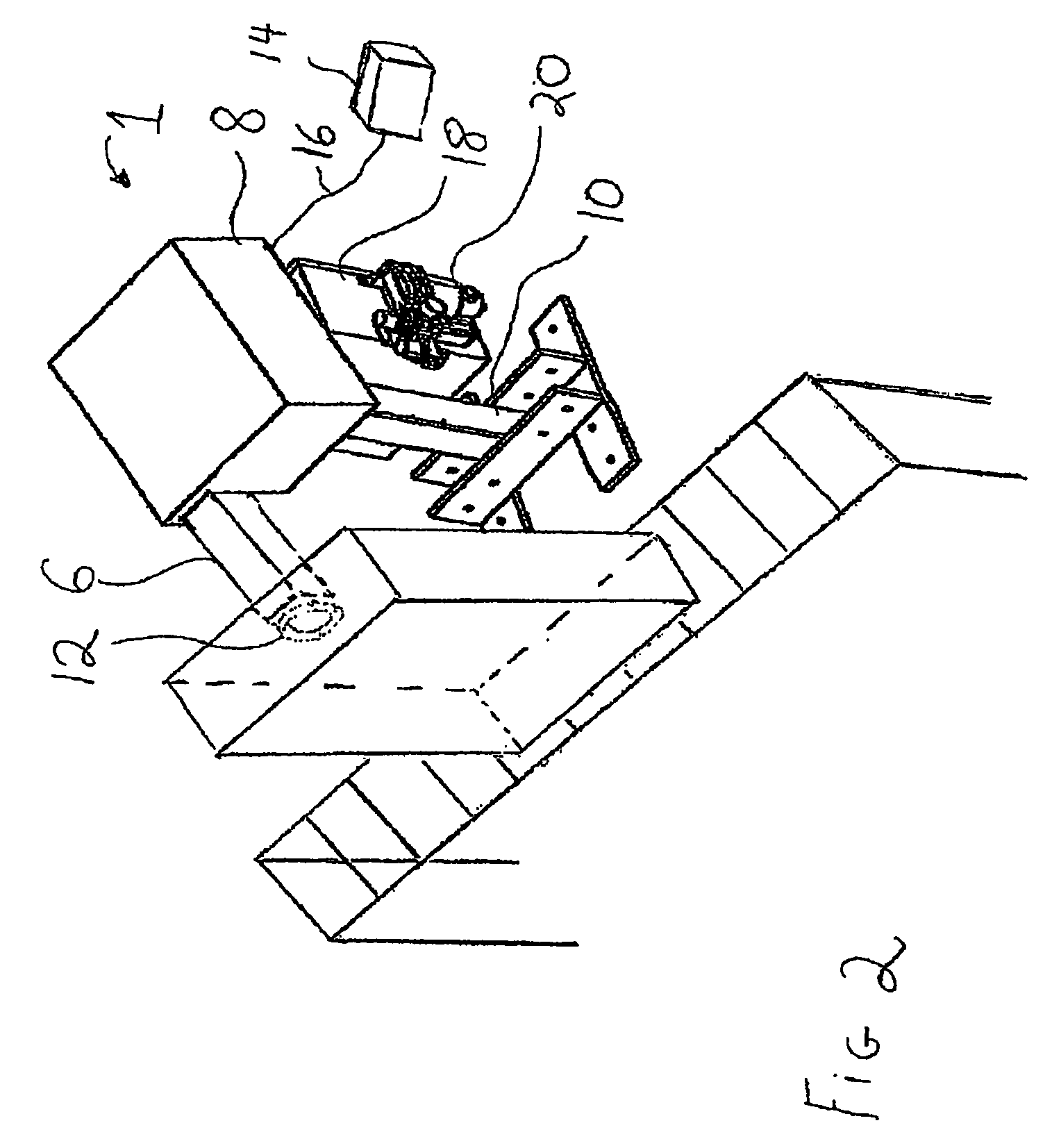
[0116]A laser generator was used to generate a laser beam from a diode pumped fiber of the wavelength of about 1064 nm having an intensity of about 20 watts. A part, in this case an aluminum housing / case of an automotive transmission, was brought by a conveying line in front of the laser marking system and device of the present invention. The transmission case was stopped in front of the safety seal assembly for a total period of about 25 seconds. The safety seal assembly was advanced via a pneumatically activated slide towards the transmission case and made physical contact with the part, with forward advancement stopped when at least one proximity switch and the sealing head made contact with the surface of the transmission case to be marked. Upon making contact with the transmission case, the transmission case together with the inner vacuum cup formed the marking chamber, while the transmission case together with the inner and outer vacuum cups formed the vacuum chamber. A vacuum...


PUM

PropertyMeasurementUnit
wavelengthaaaaaaaaaa
vacuumaaaaaaaaaa
movementaaaaaaaaaa

Abstract

The present invention is directed to a laser marking device, system and method for its use.

Description

CROSS REFERENCES TO RELATED APPLICATIONS[0001]The present application claims priority of U.S. Provisional Patent Application Ser. No. 60 / 775,558 filed Feb. 22, 2006 entitled “Laser Marking System” filed in the name of Eric McElroy et al.STATEMENT REGARDING FEDERALLY SPONSORED RESEARCH OR DEVELOPMENT[0002]Not applicable.NAMES OF PARTIES TO A JOINT RESEARCH AGREEMENT[0003]Not applicable.REFERENCE TO A SEQUENCE LISTING OR OTHER MATERIALS[0004]Not applicable.BACKGROUND OF THE INVENTION[0005]1. Field of the Invention[0006]The present invention is directed to a laser marking device, system and method for its use.[0007]2. Description of the Related Art[0008]Laser marking systems have been known in the art.[0009]One challenge with such devices and / or systems is to know when the part to be marked is properly positioned before the marking head, and that the part or other item to be marked is not deformed or otherwise compromised.[0010]Another challenge is preventing the laser light from escap...

Claims


Application Information

Patent Timeline
Patent Type & Authority Applications(United States)
IPC IPC(8): B23K26/00
CPCB23K26/032B23K26/12B23K26/365B23K26/123B23K26/122B41M5/262B41M5/267B23K26/1224B23K26/361
Inventor MCELROY, ERIC R.HOCKENBERRY, TODD L.SWEET, DAVID M.
Owner MECCO PARTNERS
Why Eureka
Try Eureka