Pair of pressing jaws for hydraulic or electric pressing tools

Inactive Publication Date: 2008-01-24
GUSTAV KLAUKE GMBH
View PDF60 Cites 5 Cited by
  • Summary
  • Abstract
  • Description
  • Claims
  • Application Information

AI Technical Summary

Benefits of technology

[0010] An integrated securing part gives the advantage of it being possible for the tension spring to be connected to the pressing jaw of a pair of pressing jaws directly and without any further fastening means being used. As an integral constituent part of the pressing jaw, the securing part cannot get lost and, during assembly, fewer individual parts have to be assembled. In order to secure the tension spring, a preferably hook-like end of the tension spring engages around the crosspiece, which runs transversely to the accommodating opening. The crosspiece may run, for example, parallel to the longitudinal extent, or also in the direction of the thickness, of the pressing jaw. The crosspiece preferably has both ends connected to the pressing jaw. It is also possible for the crosspiece only to have one end fixedly connected to the pressing jaw. The securing part can be produced by casting, in conjunction with the production of the pressing jaw (for example in the lost-wax process). It is also conceivable, however, for the securing part to be produced, for example, by a metal removal operation.

Problems solved by technology

These stops preferably interact with the pressing-tool accommodating neck, which is fixed in relation to the pressing jaws, both the open position and the closed position of the pressing mouth, furthermore, being stop-limited as a result of this configuration.

Method used


Image

  • Pair of pressing jaws for hydraulic or electric pressing tools
  • Pair of pressing jaws for hydraulic or electric pressing tools
  • Pair of pressing jaws for hydraulic or electric pressing tools

Examples


first embodiment

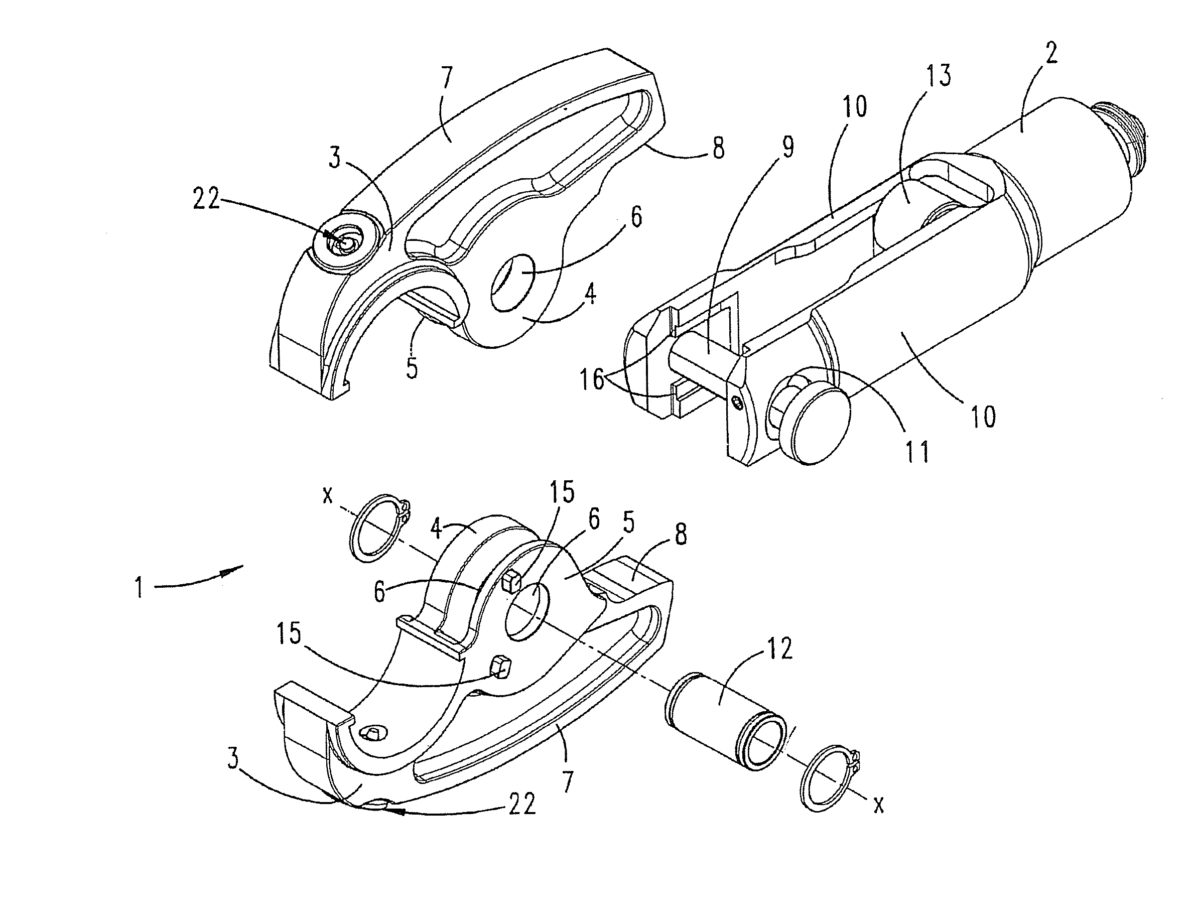
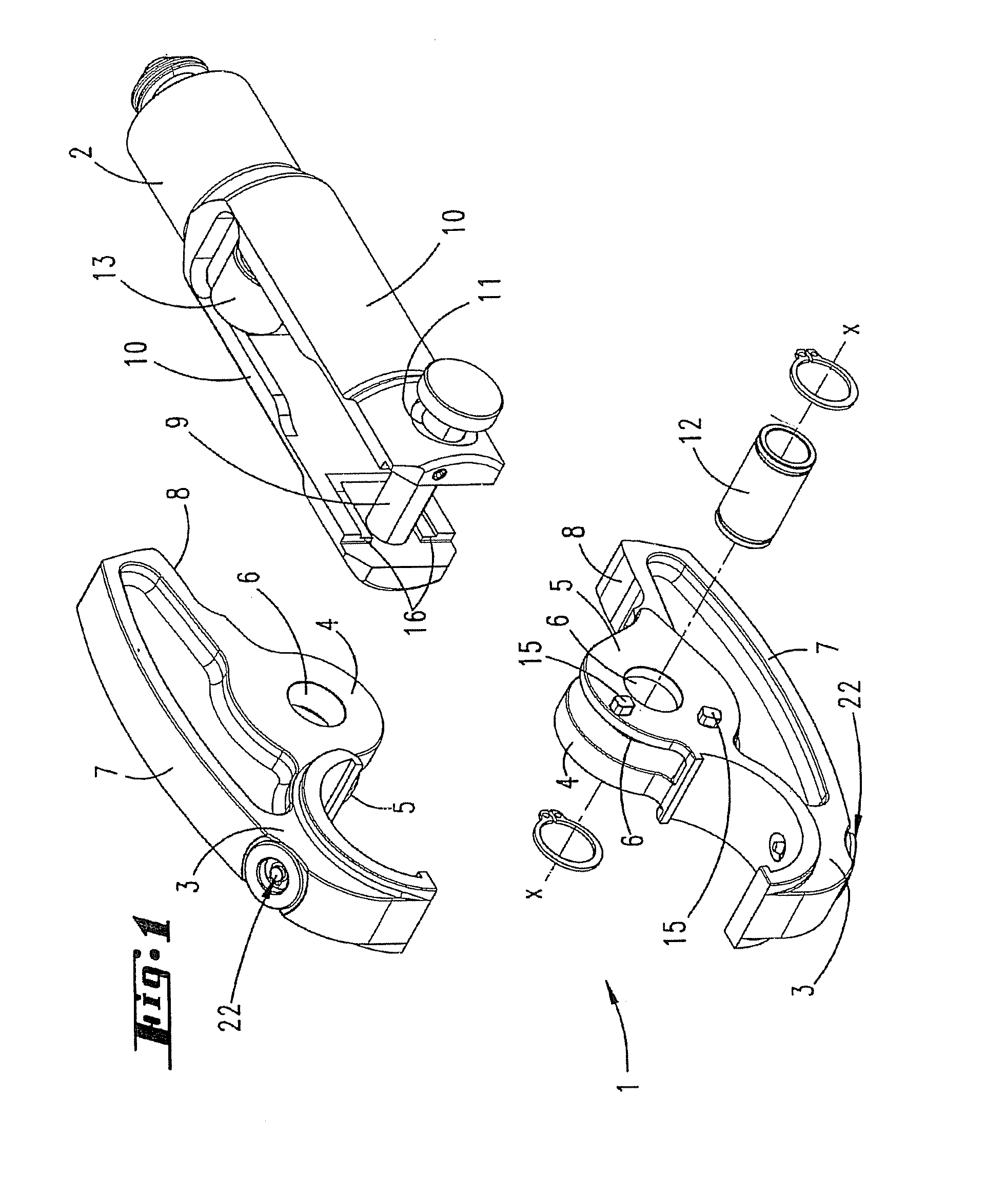
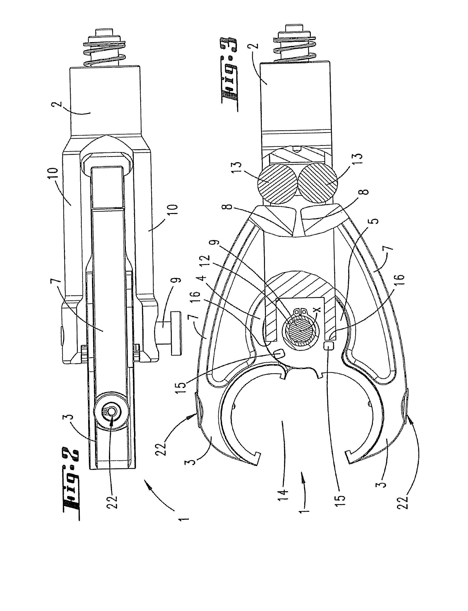
[0048] Illustrated and described, in the first instance with reference to FIG. 1, of a pair 1 of pressing jaws, in a first embodiment, for a hydraulic or electric pressing tool, merely an accommodating neck 2 of the latter, for accommodating a pair 1 of pressing jaws, being shown in the illustrations.

[0049] The two pressing jaws 3 are configured identically to one another and each have two bearing eyes 4, 5 with coaxial bearing openings 6.

[0050] The pressing jaws 3 are part of a pressing lever 7 which, on one side of the bearing opening 6, forms the pressing jaw 3 and, on the other side of the bearing opening 6, forms a curved track B.

[0051] The bearing eyes 4, 5 of each pressing jaw 3 have different thicknesses, as measured in the axial direction of the bearing openings. The bearing eye 4 is thus approximately three times the thickness of the bearing eye 5.

[0052] The clear distance between the two bearing eyes 4 and 5 corresponds approximately to the thickness of the thicker bea...

second embodiment

[0062] The pressing jaws 3 of the second embodiment are preloaded into their open position, which is illustrated for example in FIG. 8, a tension spring 17 being provided for this purpose. This tension spring is disposed in order to engage over the separating joint F between the pressing levers 7 of the pressing jaws 3 and is positioned, in each pressing jaw, in an accommodating bore 18 which opens out into that narrow peripheral side of the pressing jaw 3 which is directed toward the separating joint F. The two accommodating bores 18 of the pressing jaws 3 are disposed opposite one another. These accommodating bores 18 open out, at the other end, into bores 19 which pass through the pressing jaw 3, transversely to the direction in which the tension spring 17 extends, in the region of the pressing lever 7. Positioned in each of these bores 19 is a retaining pin 20 which receives the respective end of the tension spring 17 and in this respect, in interaction with the wall of the bore...


PUM

PropertyMeasurementUnit
diameteraaaaaaaaaa
areaaaaaaaaaaa
thicknessaaaaaaaaaa

Abstract

The invention relates to a pair of pressing jaws for hydraulic or electric pressing tools for pressing fittings onto pipes or for the press connection of electric cables, two pressing jaws connected to one another in an articulated manner forming a pair of pressing jaws, the pressing jaws being biased into their open position by a tension spring which spans a free space between the two pressing jaws, and in each case one end of the tension spring being accommodated in an accommodating opening which opens out into a narrow peripheral side of the pressing jaw, this narrow peripheral side being directed toward the free space, and, in order to secure the tension spring, a tension-spring end engaging around a pin-like securing part, which securing part is disposed at that end of the accommodating opening which is directed away from the free space. In order to secure the tension spring in a functionally advantageous manner, it is provided that the securing part is formed as an integral crosspiece of the pressing jaw.

Description

[0001] This application is a continuation-in-part of pending U.S. Ser. No. 11 / 534,737, herein incorporated by reference, filed on Sep. 25, 2006, which is a divisional application of U.S. Ser. No. 10 / 884,752 filed on Jul. 2, 2004, herein incorporated by reference, now U.S. Pat. No. 7,216,523. This application claims priority from German Patent Application No. DE 202006013693.2, filed Sep. 7, 2006, herein incorporated by reference. FIELD OF THE INVENTION [0002] The invention relates, to a pair of pressing jaws for hydraulic or electric pressing tools for pressing fittings onto pipes or for the press connection of electric cables, the two pressing jaws being disposed for rotation about a common axis of rotation and each pressing jaw forming a bearing eye for this purpose. BACKGROUND OF THE INVENTION [0003] Pairs of pressing jaws of the type in question are known and are used, inter alia, for pressing fittings onto pipes, particularly in the sanitary sector. Such pairs of pressing jaws ...

Claims


Application Information

Patent Timeline
Patent Type & Authority Applications(United States)
IPC IPC(8): B21D37/00
CPCH01R43/042B21D39/04
Inventor FRENKEN, EGBERT
Owner GUSTAV KLAUKE GMBH
Why Eureka
Try Eureka