Drive train for a motor vehicle and method for starting an internal combustion engine and method for generating electric current

a technology of internal combustion engine and drive train, which is applied in the direction of electric energy vehicles, transmission elements, toothed gearings, etc., can solve problems such as electric machines, and achieve the effect of increasing the free spa

Active Publication Date: 2005-12-22
GETRAG GETRIEBE & ZAHNRADFABRIK HERMANN HAGENMEYER GMBH & CO KG
View PDF18 Cites 25 Cited by
  • Summary
  • Abstract
  • Description
  • Claims
  • Application Information

AI Technical Summary

Benefits of technology

[0065] In this embodiment it is also particularly favorable that a standardized and maintenance-free shift clutch can be arranged in the interior of the transmission housing in order to bring about a shiftable connection to the crankshaft. In other words it is not necessary to provide shifting means, which require particular maintenance or encapsulation, outside the transmission.
[0066] It is also considered advantageous if the connection between the output shaft of the electric machine and the crankshaft is made via a shaft which is arranged parallel to the input shaft of the step-by-step variable speed transmission.
[0067] In this embodiment it is possible to arrange the separate shaft in a structurally favorable fashion so that a larger amount of free space is provided for the arrangement of the electric motor, in particular on the outside of the transmission housing.

Problems solved by technology

An electric machine which is arranged in the transmission permits both boosting of the traction force and recuperation but frequently does not allow the electric machine to be operated as a starter generator since generally not only the friction clutch but also at least one of the clutches of the step-by-step variable speed transmission have to be closed in order to drive the internal combustion engine.

Method used


Image

  • Drive train for a motor vehicle and method for starting an internal combustion engine and method for generating electric current
  • Drive train for a motor vehicle and method for starting an internal combustion engine and method for generating electric current
  • Drive train for a motor vehicle and method for starting an internal combustion engine and method for generating electric current

Examples


first embodiment

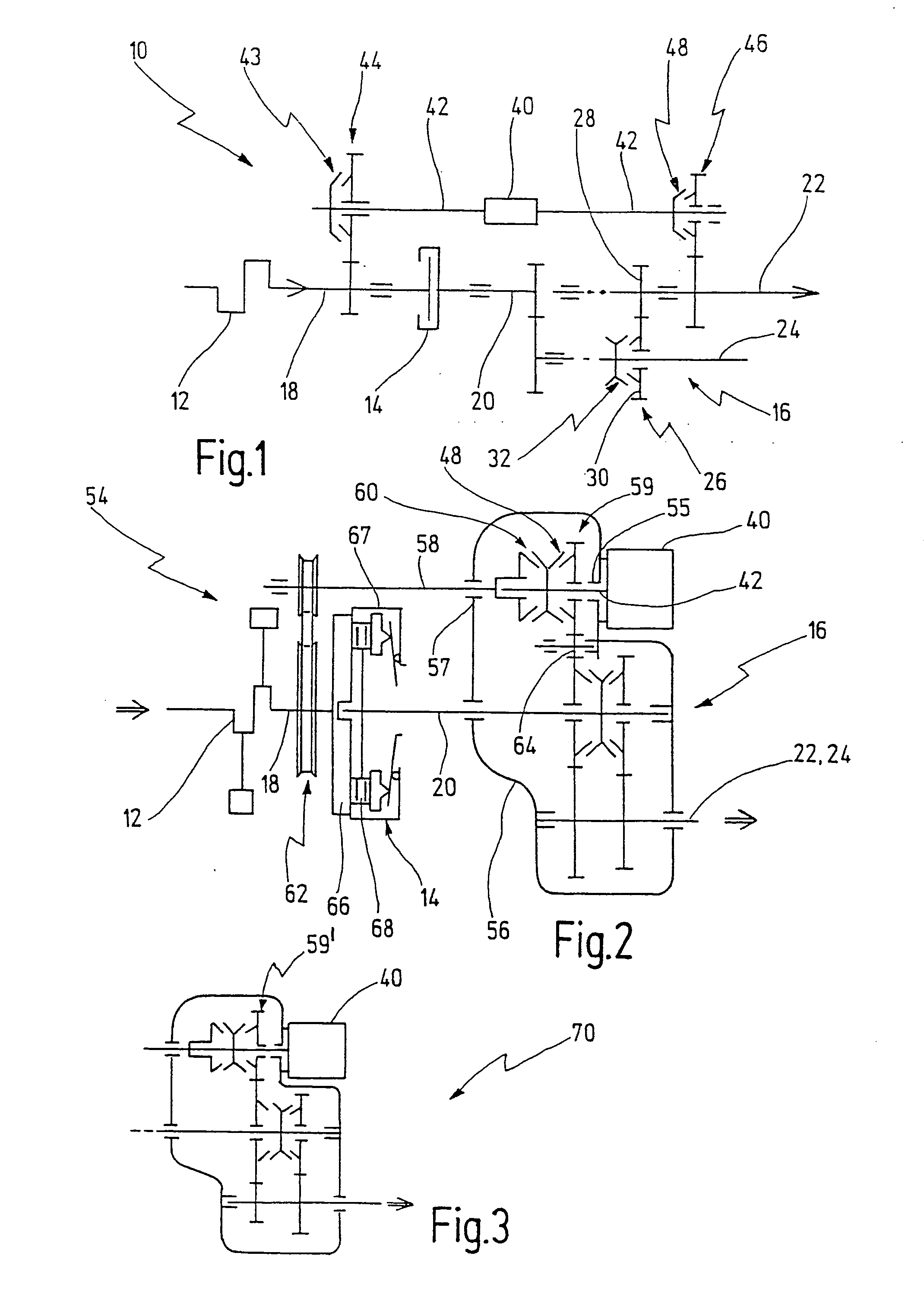
[0094] In FIG. 1, a drive train according to the invention is designated generally by 10.

[0095] The drive train 10 can be mounted in a motor vehicle (not illustrated in more detail) which is driven by an internal combustion engine 12.

[0096] The drive train 10 has a friction clutch 14 and a step-by-step variable speed transmission 16.

[0097] The friction clutch 14 is embodied as a driving-off and separating clutch and is usually in the form of a dry clutch. It can however also be embodied as a wet clutch.

[0098] An input element of the friction clutch 14 is connected to a crankshaft 18 of the internal combustion engine 12. An output element of the friction clutch 14 is connected to an input shaft 20 of the step-by-step variable speed transmission 16.

[0099] An output shaft 22 of the step-by-step variable transmission 16 is connected to drive wheels of the motor vehicle via a differential gear (not illustrated).

[0100] The step-by-step variable speed transmission 16 is embodied as a ...

second embodiment

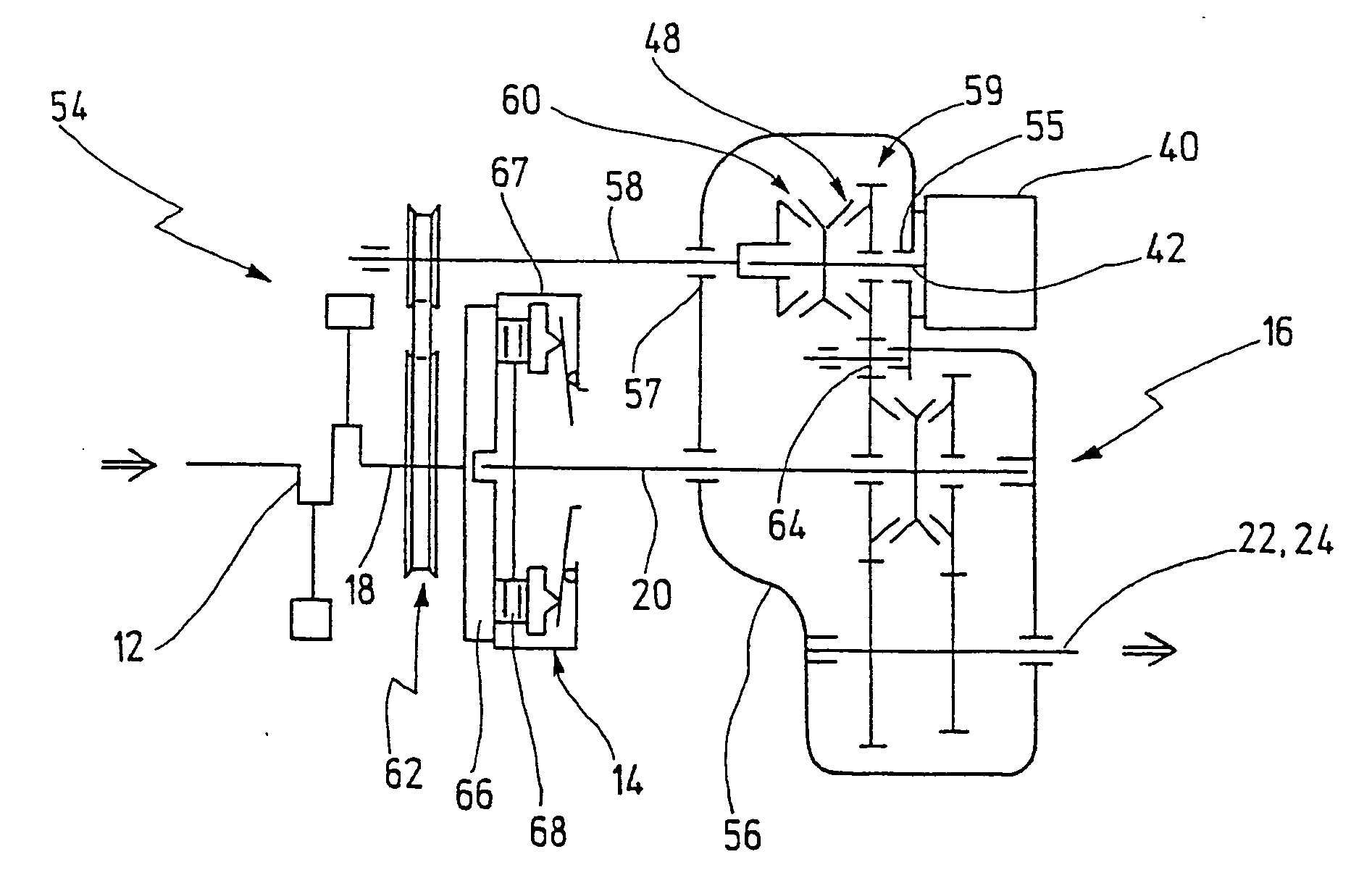
[0119] In FIG. 2, the drive train according to the invention is generally designated by 54.

[0120] The housing of the step-by-step variable speed transmission 16 is shown in FIG. 2 at 56. It is to be noted that the electric machine 40 is connected by flanges to the outside of the housing 56, the output shaft 42 being led into the interior of the housing 56 via a shaft seal 55.

[0121] A secondary shaft 58 which is provided as an extension of the output shaft 42 extends from the interior of the housing 56 out of the other end of the housing 56 via a shaft seal 57. The secondary shaft 58 extends here parallel to the transmission input shaft 20 and passes the friction clutch 14.

[0122] The step-by-step variable speed transmission 16 is embodied in the illustrated embodiment as a transverse transmission, the countershaft 24 simultaneously forming the output shaft 22 of the step-by-step variable speed transmission 16.

[0123] In the illustrated embodiment, the part of the secondary shaft 58...

third embodiment

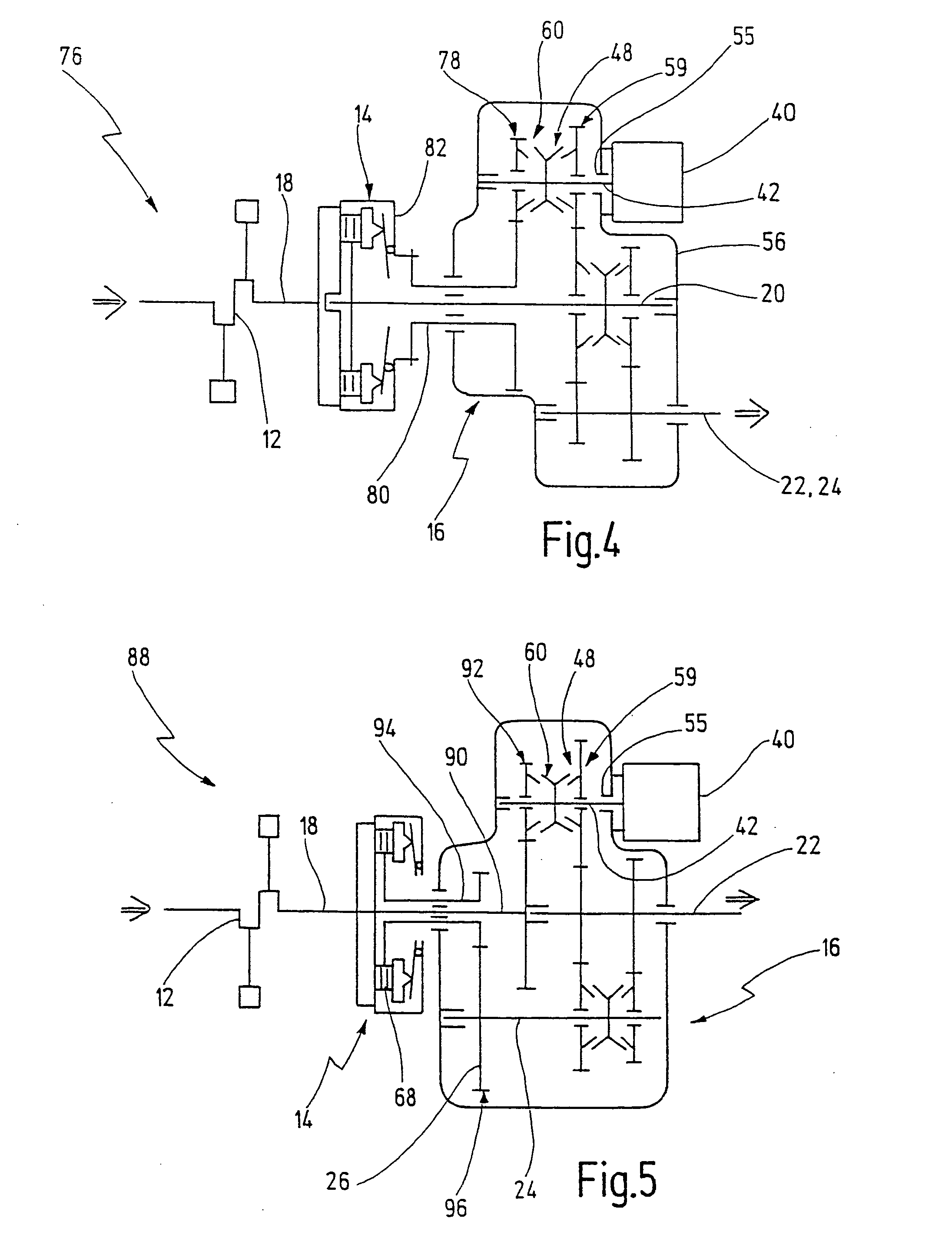
[0134]FIG. 4 shows a drive train 76 according to the invention.

[0135] In the drive train 76, the output shaft 42, extending into the interior of the transmission housing 56, of the electric machine 40 can be connected to a secondary shaft 80 in the form of a hollow shaft via a wheel set 78. In this embodiment, the hollow shaft 80 is connected fixed in terms of rotation to the clutch basket 82, and consequently fixed in terms of rotation to the crankshaft 18.

[0136] The transmission input shaft 20 extends through the hollow shaft 80.

[0137] This embodiment has the advantage in comparison with the drive train 54 that the connection between the output shaft 42 of the electric machine 40 and the crankshaft 18 is made via a rotational element (in the form of the hollow shaft 80) which is arranged concentrically with respect to the transmission input shaft 20. Consequently, the installation space can be kept small in the radial direction. There is no need for a shaft leading past the fric...


PUM


Abstract

A drive train is proposed for a motor vehicle which is driven by an internal combustion engine, having a single friction clutch which has an input element and an output element, wherein the input element is to be connected to a crankshaft of the internal combustion engine; a step-by-step variable speed transmission which has an input shaft connected to the output element of the friction clutch; and an electric machine which can be connected via a clutch to an output shaft of the step-by-step variable speed transmission in order to be able to apply traction force to the output shaft when the friction clutch is opened or closed, and which can be connected as a starter generator to the crankshaft in order to start the internal combustion engine or be driven by the internal combustion engine. The electric machine can be connected fixed in terms of rotation to the crankshaft while bypassing the friction clutch in order, in this way, to start the internal combustion engine when the friction clutch is opened or to be driven by the internal combustion engine.

Description

CROSS REFERENCE TO RELATED APPLICATIONS [0001] This application is a continuation of International Application PCT / EP03 / 11349, which application is hereby incorporated by reference in its entirety. BACKGROUND OF THE INVENTION [0002] 1. Field of the Invention [0003] The present invention relates to a drive train for a motor vehicle which is driven by an internal combustion engine, having: [0004] an individual friction clutch which has an input element and an output element, wherein the input element is to be connected to a crankshaft of the internal combustion engine; [0005] a step-by-step variable speed transmission which has an input shaft, a multiplicity of wheel sets corresponding to a multiplicity of gear speeds, and an output shaft, wherein the input shaft is connected to the output element of the friction clutch; and [0006] an electric machine which can be connected via a clutch to the output shaft of the step-by-step variable speed transmission in order to be able to apply tr...

Claims


Application Information

Patent Timeline
Patent Type & Authority Applications(United States)
IPC IPC(8): B60K6/48B60K6/547F02N11/04F02N15/02F16H3/089F16H3/091F16H3/12
CPCB60K6/48Y10S903/946F02N11/04F02N15/006F02N15/025F16H3/089F16H3/0915F16H3/126F16H2003/0818F16H2200/0034F16H2200/0052Y02T10/6221Y10T477/32Y10T477/71B60K6/547B60K2006/4816Y02T10/62B60K2006/268
Inventor SEUFERT, MARTINKIESSLING, HANNESSCHAARSCHMIDT, REINHARD
Owner GETRAG GETRIEBE & ZAHNRADFABRIK HERMANN HAGENMEYER GMBH & CO KG
Why Eureka
Try Eureka