Adaptor assembly

a technology for adaptors and parts, applied in the direction of coupling contact members, coupling device connections, coupling/disconnecting parts, etc., can solve the problems of reducing the possibility of reducing difficult welding process, difficult to watch, etc., and achieve the effect of reducing the internal space and minimizing the volume of the adaptor

Inactive Publication Date: 2005-03-01
DELTA ELECTRONICS INC +1
View PDF13 Cites 32 Cited by
  • Summary
  • Abstract
  • Description
  • Claims
  • Application Information

AI Technical Summary

Benefits of technology

The main purpose of the present invention is to provide an adaptor assembly, which is able to reduce the internal space and minimize the volume of the adaptor.

Problems solved by technology

Therefore, the power connecting cord 66 occupies large internal space of the adaptor, which largely lowers the possibility to reduce the volume of the adaptor.
Since the insulation housing 13 is a structure with five-sides hunt, the welding process is difficult to perform and hard to watch.
The welding result is often not complete.
Besides, during the welding process, the extremely high heat will be unavoidably conducted through the conductive terminal 15, which will easily damage the insulation housing 13 and the mounting situation of the conductive terminal 15, even make the whole insulation housing 13 unusable.
Therefore, the welding process not only costs lots of time and energy in the whole assembly process for the adaptor, but also affects the structural quality after the assembly is accomplished.
In addition, the quite long length of the power connecting cord 66, which is necessary for conveniently executing the welding process, will be too long after the welding is accomplished.
It is very possible to cause malfunction of the adaptor since the electronic elements are compressed in the limited space.
Besides, a dangerous short circuit might occur if the insulation coating of the power connecting cord 66 is damaged during the compressive assembly process or the power connecting cord 66 has an insulation flaw in the first place.

Method used


Image

  • Adaptor assembly
  • Adaptor assembly
  • Adaptor assembly

Examples


Embodiment Construction

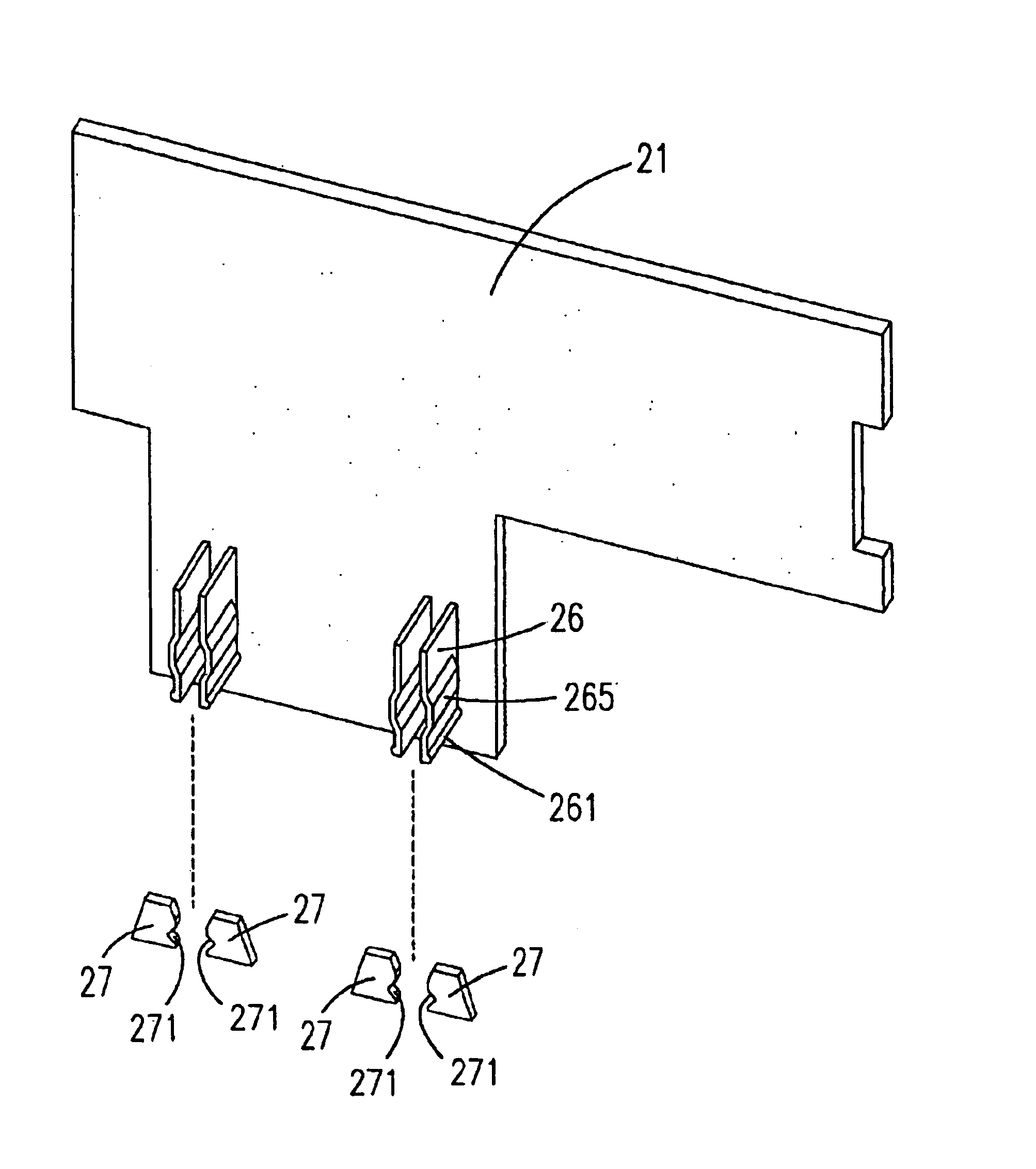
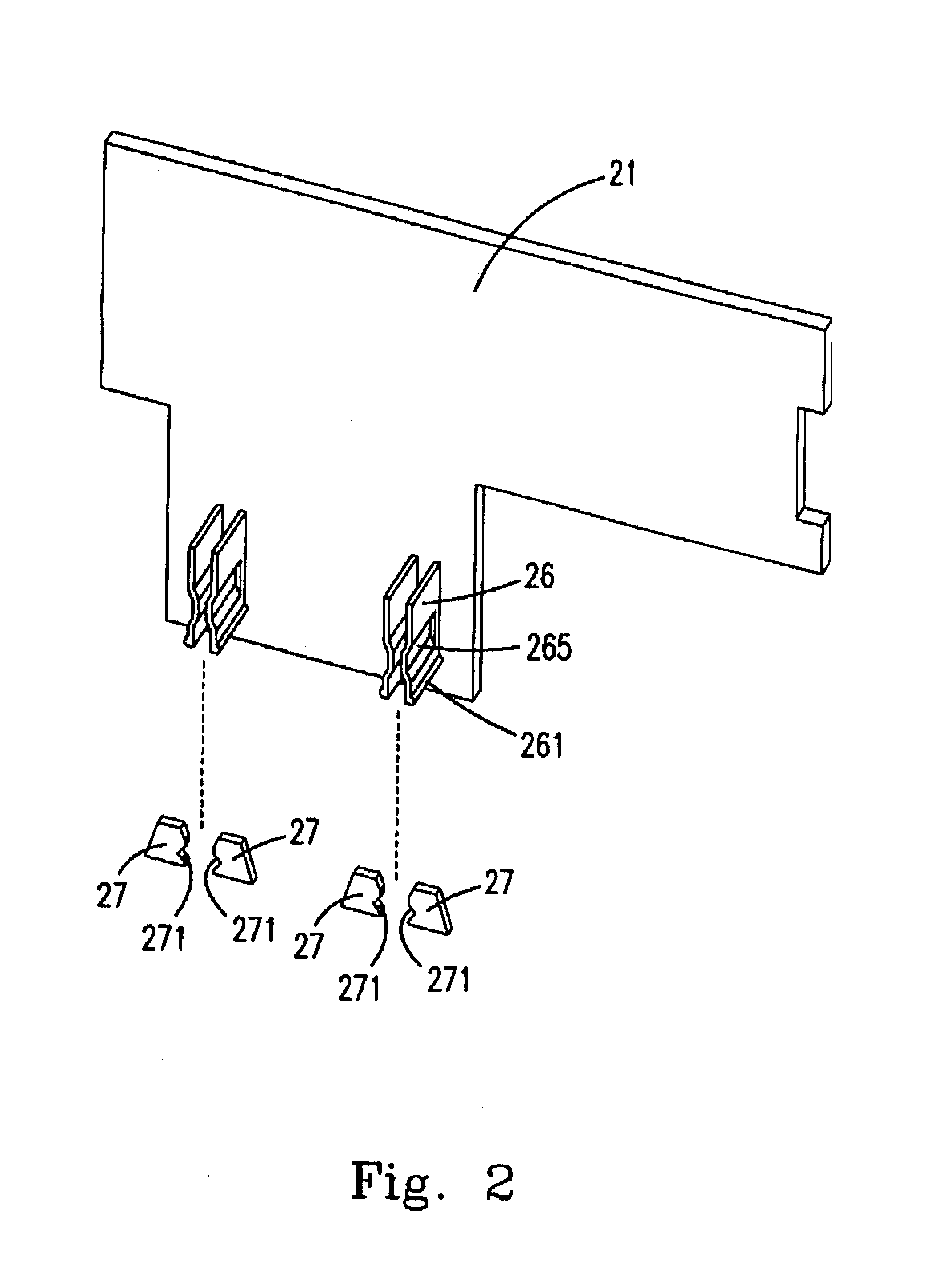
The present invention will now described more specifically with reference to the following embodiments. Please refer to FIG. 2-4. FIG. 2 is a diagram illustrating the securing mechanism in the adaptor assembly structure according to a preferred embodiment of the present invention. FIG. 3 is a diagram illustrating the securing mechanism in the adaptor assembly structure according to a preferred embodiment of the present invention. FIG. 4 is a diagram illustrating the adaptor assembly structure according to a preferred embodiment of the present invention. The adaptor basically includes a housing 23, a plug 22, and a printed circuit board 21. The plug 22 is used for electrically connecting with the external power supply. The printed circuit board 21 has different electrical elements or devices mounted thereon (not disclosed) in response to the different functions of different adaptors. According to the different purposes of different adaptors, the printed circuit board 21 can commutate...


PUM


Abstract

An adaptor assembly is provided. The adaptor assembly includes: a circuit board, a plug having a first engaging structure, securing structure fixed to the circuit board and having a second engaging structure for being electrically connected and engaging with the first engaging structure, and a housing for fixedly mounting thereon the plug. The provided adaptor assembly is able to minimize the volume of the adaptor by saving the internal space and simplify the assembly process by directly connecting the conductive terminal and the printed circuit board.

Description

FIELD OF THE INVENTIONThe present invention is related to an adaptor, and more particularly, to an adaptor assembly.BACKGROUND OF THE INVENTIONAdaptors are very common household appliances. An adaptor could be the charger for a cell phone or the power supply for a walkman. Generally, an adaptor is widely used for different purposes. When the adaptor is used as a power adaptor, it can commutate the electric current and transform the current for the directly usage of the electric equipment. When the adaptor is used as a charger, it can recharge the rechargeable battery. Please refer to FIG. 1 is a diagram illustrating the conventional adaptor assembly structure according to the prior art. The conventional adaptor assembly includes an insulation housing 13, a plug 12, a printed circuit board 11, and a power connecting cord 66. The plug 12 is used for connecting with the external power supply. The printed circuit board 11 has different electrical elements or devices (not disclosed) moun...

Claims


Application Information

Patent Timeline
Patent Type & Authority Patents(United States)
IPC IPC(8): H01R31/06
CPCH01R31/06H01R24/68H01R2103/00
Inventor EKKUL, JESSADACHAISRI, BHUMCHAILIM CHOO SOO, JAMES
Owner DELTA ELECTRONICS INC
Why Eureka
Try Eureka