Electronic component with moveable part

a technology of electronic components and moving parts, applied in the field of electronic components, can solve problems such as breakage of electronic components, and achieve the effect of effective waterproofing and avoiding a reduction in internal spa

Inactive Publication Date: 2016-12-08
TOKYO COSMOS ELECTRIC CO LTD
View PDF6 Cites 2 Cited by
  • Summary
  • Abstract
  • Description
  • Claims
  • Application Information

AI Technical Summary

Benefits of technology

[0021]According to the present invention, a movable-part-equipped electronic component capable of effectively performing waterproofing while avoiding a reduction in the internal space as much as possible can be implemented.

Problems solved by technology

For this reason, when liquid spills over the electronic component, the liquid enters inside the electronic component from the gap and may break the electronic component.

Method used


Image

  • Electronic component with moveable part
  • Electronic component with moveable part
  • Electronic component with moveable part

Examples


embodiment 1

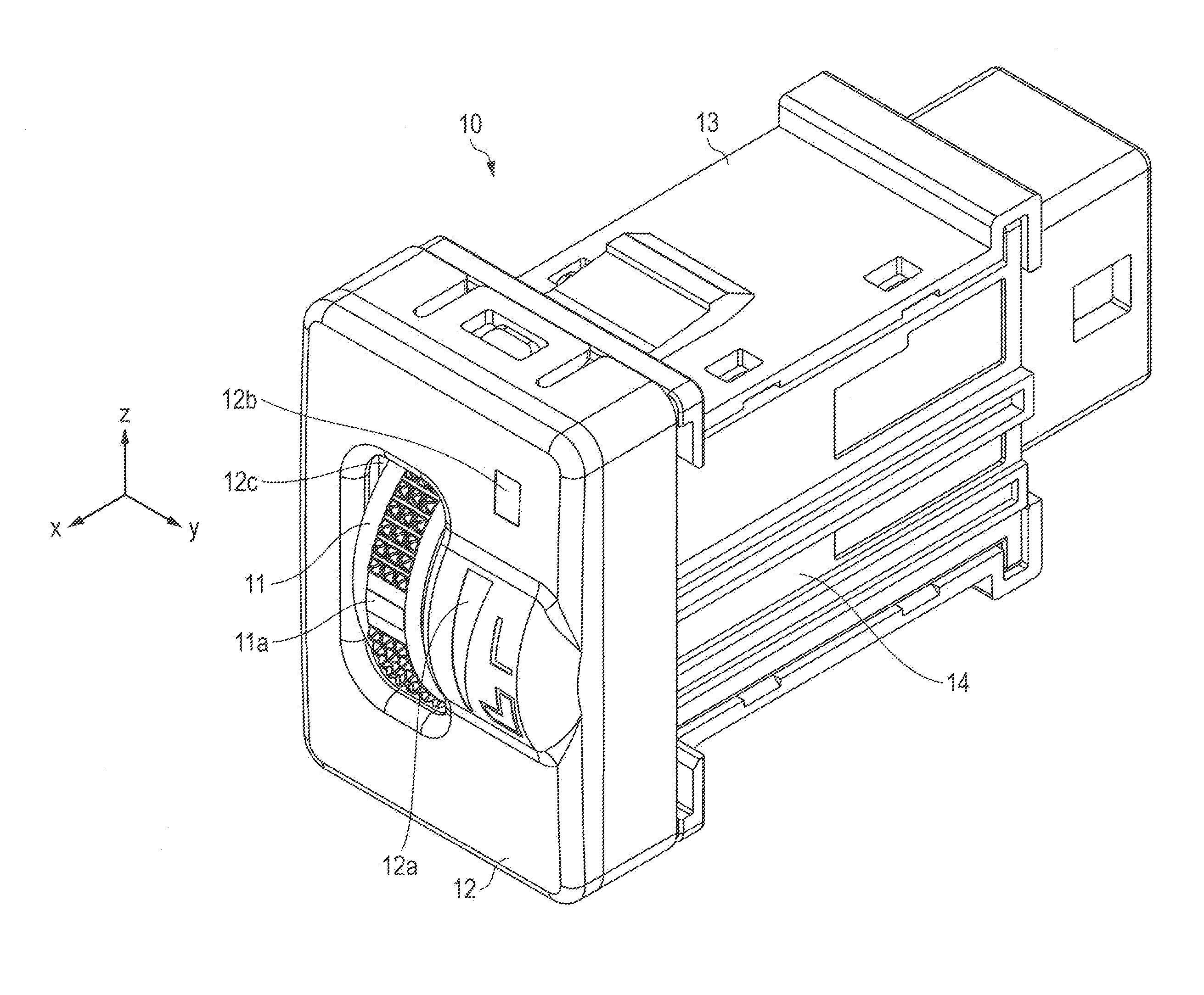
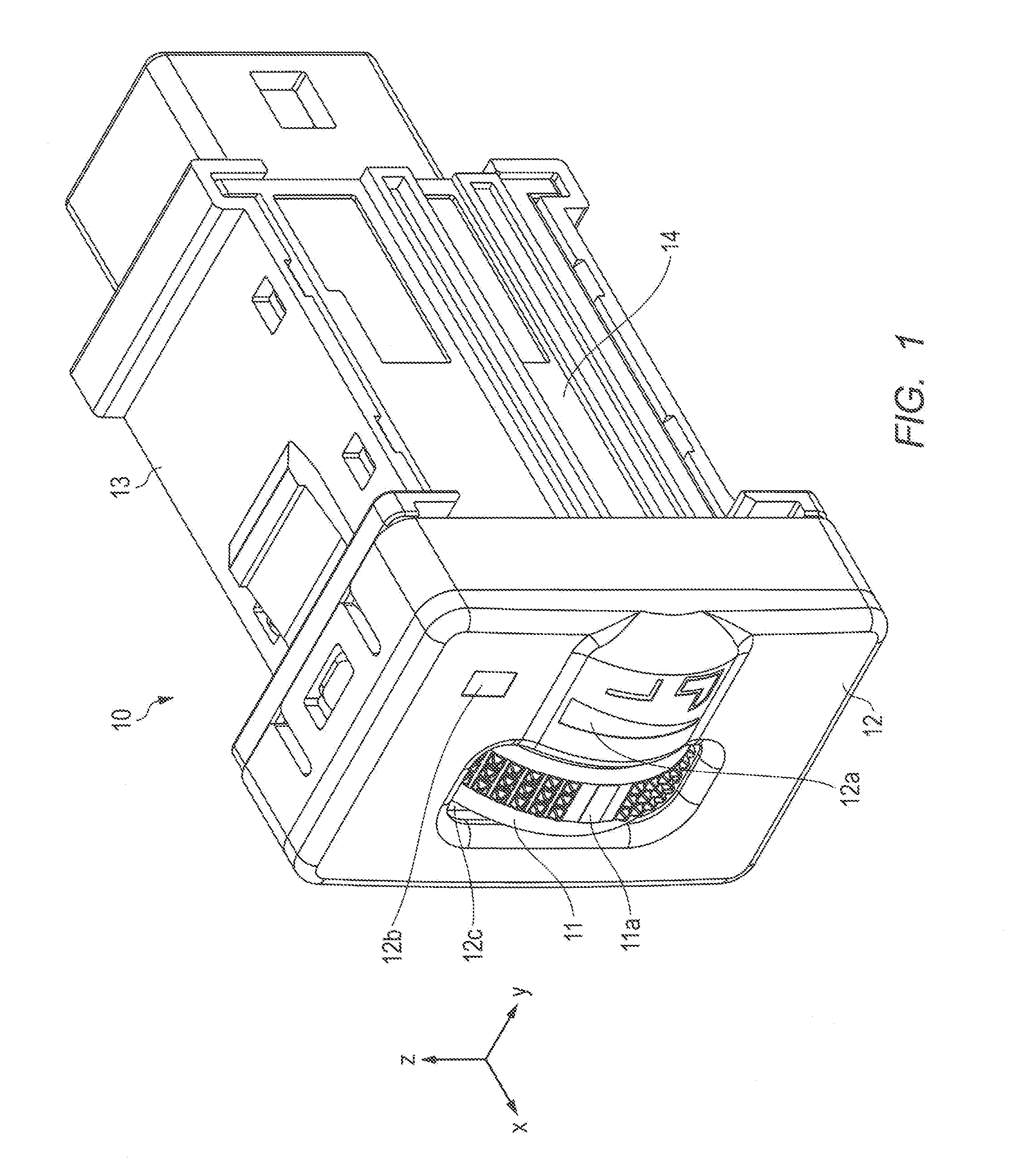
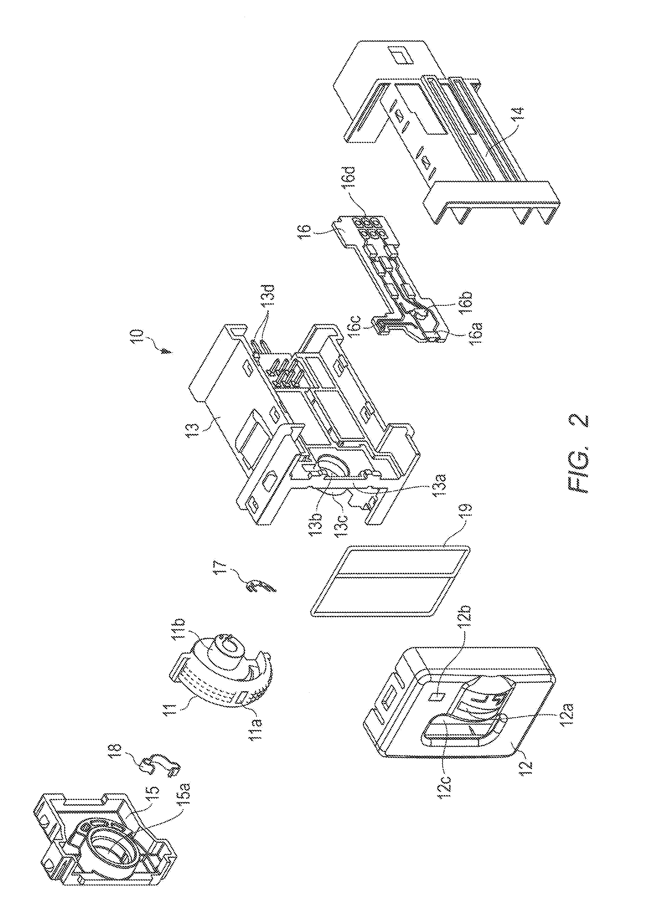
[0032]FIG. 1 is a perspective view illustrating an exemplary configuration of movable-part-equipped electronic component 10 according to Embodiment 1 of the present invention. FIG. 2 is an exploded view illustrating the exemplary configuration of movable-part-equipped electronic component 10 according to Embodiment 1 of the present invention.

[0033]Hereinafter, a description will be given of a case where movable-part-equipped electronic component 10 is an electronic component provided with a dial for adjusting the temperature of a seat heater of an automobile. However, movable-part-equipped electronic component 10 is not limited to this case, and may be another electronic component having a movable part.

[0034]As illustrated in FIGS. 1 and 2, movable-part-equipped electronic component 10 includes movable part 11, bezel 12, first housing member 13, second housing member 14, third housing member 15, circuit board 16, slider 17, click spring 18, and waterproof rubber 19.

[0035]Movable par...

embodiment 2

[0082]In Embodiment 1, light source 16a illuminates first window 11a and light source 16b illuminates second window 12a, but light source 16a may be configured to illuminate both first window 11a and second window 12a to reduce the number of light sources.

[0083]Thus, a movable-part-equipped electronic component that lights up first window 11a formed in movable part 11 and second window 12a formed in bezel 12 can be implemented while the number of parts is reduced. Hereinafter, a description will be given of movable-part-equipped electronic component 10 according to Embodiment 2 in detail.

[0084]As in movable-part-equipped electronic component 10 described in Embodiment 1, movable-part-equipped electronic component 10 according to Embodiment 2 includes movable part 11, bezel 12, first housing member 13, second housing member 14, third housing member 15, circuit board 16, slider 17, click spring 18, and waterproof rubber 19, as illustrated in FIG. 1.

[0085]FIG. 9 is a cross-sectional vi...


PUM


Abstract

The purpose of the present invention is to effectively carry out waterproofing, while avoiding cramping an internal space to the extent it is possible to do so. The component is provided with: a light source (16a); a moveable part (11) having a first window (11a); a circuit board (16); and a housing (12, 13, 14, 15) in which is formed an opening (12b) through which the surface of the moving part (11) protrudes. The housing (12, 13, 14, 15), in combination with the moveable part (11), has dividing walls (12d, 13a) for dividing the internal space of the housing (12, 13, 14, 15) into a first space and a second space. The dividing walls (12d, 13a) support the moveable part (11), and the light source (16a) illuminates the first window (11a) through a portion (12d) of the dividing walls (12d, 13a), which are formed by transmissive members.

Description

TECHNICAL FIELD[0001]The present invention relates to an electronic component equipped with a movable part (hereinafter, referred to as “movable-part-equipped electronic component”), the movable part being disposed so as to protrude from an opening portion of a housing, including a lighting window formed therein and being movable by operation of an operator.BACKGROUND ART[0002]Electronic components each provided with a rotary movable part have been popular. Examples of such an electronic component include an electronic component provided with a dial for adjusting the temperature of a seat heater of an automobile and an electronic component provided with a dial for adjusting the exposure of a digital camera.[0003]In the electronic components described above, for the purpose of enabling a rotary operation of the movable part using a finger, an opening portion is formed in the housing that houses therein the movable part, and the movable part is disposed so as to protrude from the open...

Claims


Application Information

Patent Timeline
Patent Type & Authority Applications(United States)
IPC IPC(8): H01H19/02H01H19/06
CPCH01H19/06H01H19/025B60K35/00B60K37/06B60K2370/126B60K2370/691B60K2370/692H01H9/04
Inventor MIYAGI, MASARU
Owner TOKYO COSMOS ELECTRIC CO LTD
Why Eureka
Try Eureka