Device for measuring a b-component of a magnetic field, a magnetic field sensor and an ammeter

a technology of magnetic field and ammeter, which is applied in the direction of individual semiconductor device testing, galvano-magnetic hall-effect devices, instruments, etc., can solve the problems of space requirements and disadvantages of flux concentrators, show saturation effects and signs of hysteresis, and achieve cost-effective effects

Inactive Publication Date: 2004-09-23
ROBERT BOSCH GMBH
View PDF4 Cites 5 Cited by
  • Summary
  • Abstract
  • Description
  • Claims
  • Application Information

AI Technical Summary

Benefits of technology

0006] Advantageous further refinements and improvements of the device according to the present invention are specified in the dependent claims.
0007] In particular, is advantageous that an electric field, by which the charge carriers are introduced into the area, is provided between a first terminal and a second terminal. By this means, the introduction of the charge carriers and their drift through the area are realized in a simple and reliable manner.
0008] Furthermore, it is advantageous that, in order to produce the field distribution, either a lateral electric field or a lateral particle gradient or a lateral diffusion profile or the modulation of the band edges or the modulation of the Fermi levels in local space, e.g. using built-in potential barriers in nipi structures

Problems solved by technology

A disadvantage of flux concentrators is that they show saturation effects and signs of hysteres

Method used


Image

  • Device for measuring a b-component of a magnetic field, a magnetic field sensor and an ammeter
  • Device for measuring a b-component of a magnetic field, a magnetic field sensor and an ammeter
  • Device for measuring a b-component of a magnetic field, a magnetic field sensor and an ammeter

Examples


Embodiment Construction

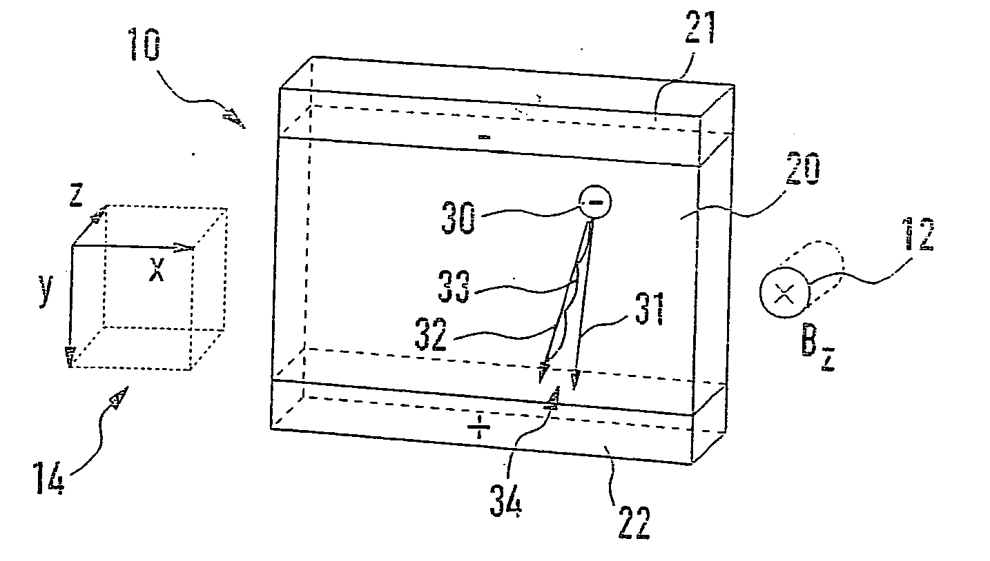
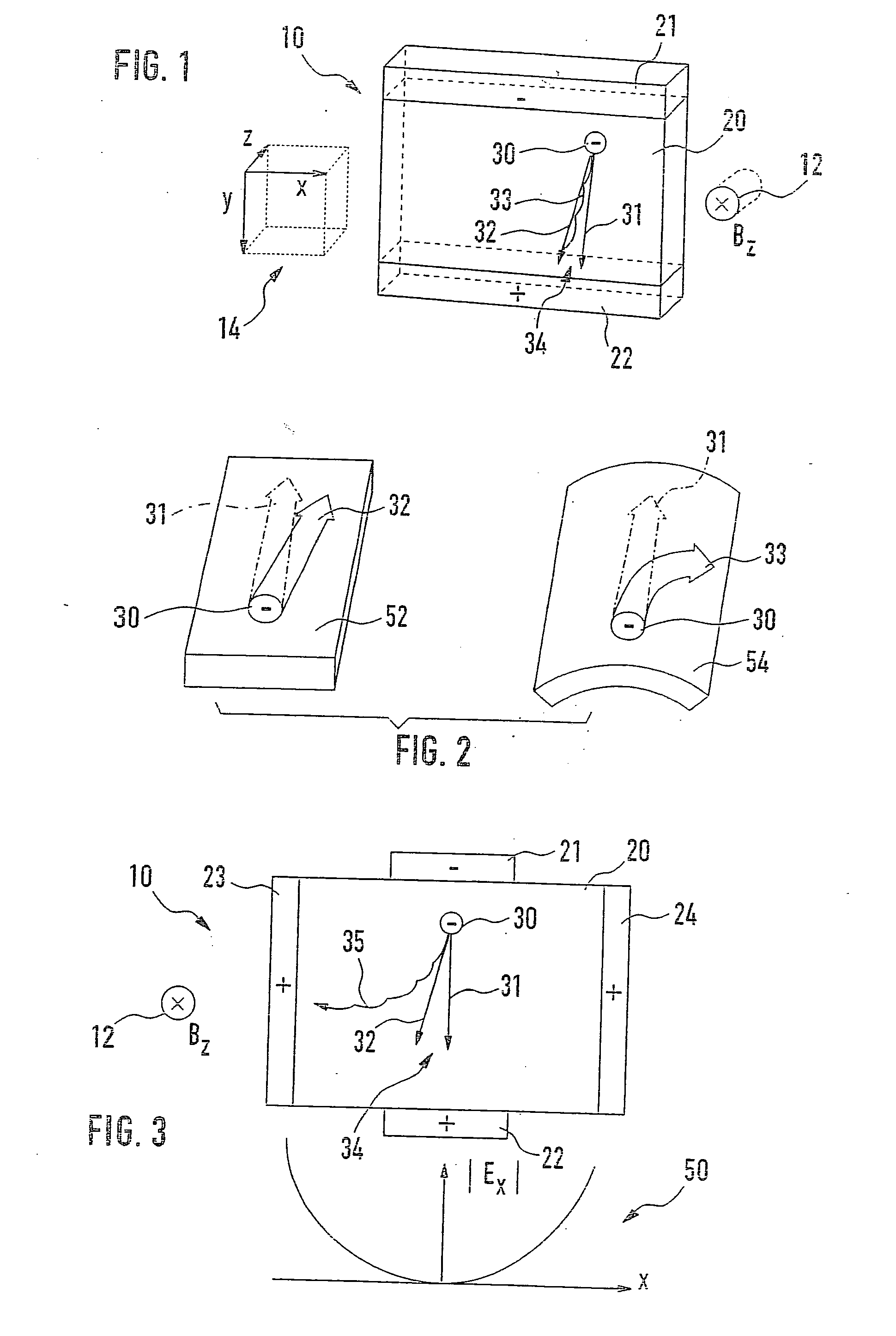
[0016] The functioning principle of a standard Hall-effect sensor 10 is schematically represented in FIG. 1. Hall-effect sensor 10 includes a region 20, which is normally provided in a semiconductor substrate. In addition, Hall-effect sensor 10 includes a first terminal 21 and a second terminal 22. Provided between first terminal 21 and second terminal 22 is an electric field not shown, through which a charge carrier 30 that is denoted in the figure by a minus sign, as a negative charge carrier 30, is moved from first terminal 21, through region 20, to second terminal 22. Accordingly, first terminal 21 is at a negative potential and denoted by a minus sign, while second terminal 22 is indicated by a positive sign and is at a positive potential. The voltage applied between first terminal 21 and second terminal 22 brings charge carrier 30 from first terminal 21 into region 20; this occurring along an introduction direction, which is designated in the figure to be in the vertical direc...


PUM


Abstract

Proposed is a device (10), a magnetic-field sensor, and an ammeter; a field distribution (50) of a first electric field being provided in a region (20) in such a manner, that the magnitude of the x component of the first electric field increases in the x direction.

Description

[0001] The present invention relates to a device for measuring a B component of a magnetic field according to definition of the species in claim 1, as well as to a magnetic-field sensor and an ammeter according to the species defined in the further, dependent claims.BACKGROUND INFORMATION[0002] The present state of technological development allows magnetic fields, e.g. of current conductors, to be measured by magnetic-field sensors, e.g. Hall-effect sensors. According to the related art, flux concentrators are used in order to be able to measure very small magnetic fields, as well, with the aid of such magnetic-field sensors. Such flux concentrators are essentially made up of high-permeability materials, which are positioned with respect to the magnetic field to be measured, in such a manner, that an increase in the measuring sensitivity results from the combination of a magnetic-field sensor and a flux concentrator. A disadvantage of flux concentrators is that they show saturation ...

Claims


Application Information

Patent Timeline
IPC IPC(8): G01R33/07H01L43/06
CPCH01L43/065G01R33/07H10N52/101
Inventor HAUENSTEIN, HENNING
Owner ROBERT BOSCH GMBH
Why Eureka
Try Eureka