Fluid reservoir

a technology of power assist system and reservoir, which is applied in the direction of positive displacement liquid engine, piston pump, machine/engine, etc., can solve the problems of high cost and loss of flexibility, no way to “limp home”, and the cost of retooling and redesigning the molds for the pump to make the reservoir an integral part of the pump is significant, so as to reduce the labor of the plant and reduce the cost of assembling. , the effect of improving the under hood appearance of the power

Inactive Publication Date: 2009-09-22
FORD GLOBAL TECH LLC
View PDF15 Cites 5 Cited by
  • Summary
  • Abstract
  • Description
  • Claims
  • Application Information

AI Technical Summary

Benefits of technology

[0007]The invention has the advantage of removing costs from a vehicle's power assist system. The elimination of the main suction hose, the hose's associated clamps, as well as a reservoir mounting bracket, result in a smaller and more efficient system. In contrast, the conventional system results in a suction hose full of fluid. In the preferred embodiment, the amount of fluid required in the overall system is reduced as well.
[0008]The invention has the further advantage of providing a more efficient and flexible power assist system without realizing the high costs of development that accompany the redesign of a conventional variable displacement pump integral to power assist systems. The power assist system described here takes advantage of an existing pump design and mounts the reservoir mounting structure by passing directly through the pump securing structure aperture and attaching to the component support structure. Although many of the pumps having reservoirs directly integrated into their housing exist today to provide space savings, the savings come with disadvantages of a high cost and a loss of flexibility. The cost associated with retooling and redesigning the molds for a pump to make the reservoir an integral part of a pump is a significant amount. Additionally, in the undesired circumstance that the reservoir portion fails, there is no way to “limp home” since removing the reservoir renders the pump useless. In contrast, the system described herein allows for the old reservoir to be removed and a temporary reservoir to be substituted into the system with hoses and clamps, etc. For work vehicles such as trucks and farm equipment used in remote locations, the flexibility of a vehicle subsystem is often beneficial.
[0011]The invention has the further advantage of reducing plant labor time. The elimination of the reservoir mounting bracket and the suction hose and its corresponding clamps, results in fewer parts to assemble. Furthermore, since one reservoir fluid outlet connects directly to the pump fluid inlet and the reservoir surface is in close proximity to the a pump surface, the two components tend to orient themselves into position during loose assembly allowing the reservoir and the pump to be assembled into final position without additional clamping.
[0012]The invention has the further advantage of improving the under hood appearance of the power assist system. The removal of the formed suction hose provides a simple, compact system with improved underhood craftsmanship.
[0013]The invention has the further advantage of providing improving the power assist system while maintaining the flexibility to end user of the motor vehicle in the event of a reservoir failure of the power assist system in the field. Because the reservoir is not integrated into the housing of the pump, the power assist system will still function if supplied with fluid. In the event the reservoir fails in the field, it can be temporarily replaced by a conventional reservoir that can receive and supply fluid to the system using conventional pipes and suction hoses. For commercial vehicles operating in remote locations, the ability to reduce the time and expense to recover a stranded vehicle is of value.

Problems solved by technology

Although many of the pumps having reservoirs directly integrated into their housing exist today to provide space savings, the savings come with disadvantages of a high cost and a loss of flexibility.
The cost associated with retooling and redesigning the molds for a pump to make the reservoir an integral part of a pump is a significant amount.
Additionally, in the undesired circumstance that the reservoir portion fails, there is no way to “limp home” since removing the reservoir renders the pump useless.

Method used


Image

  • Fluid reservoir
  • Fluid reservoir
  • Fluid reservoir

Examples


Embodiment Construction

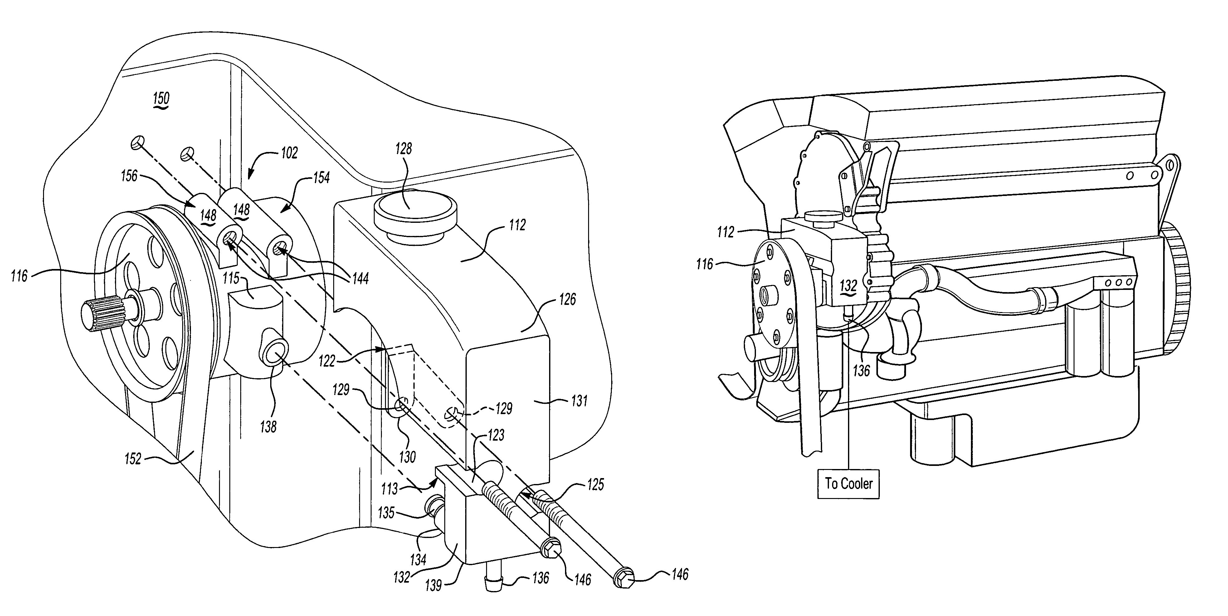
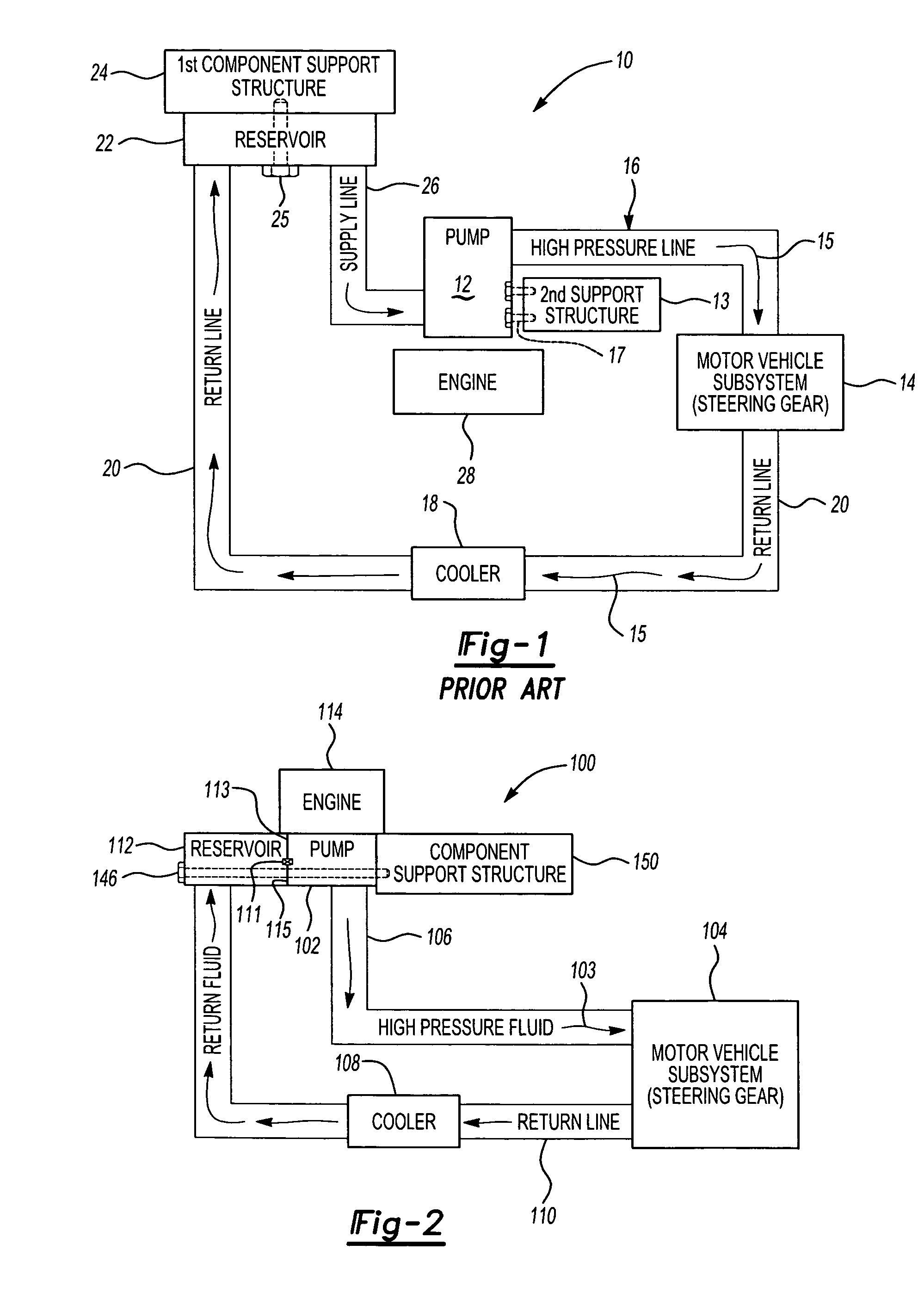
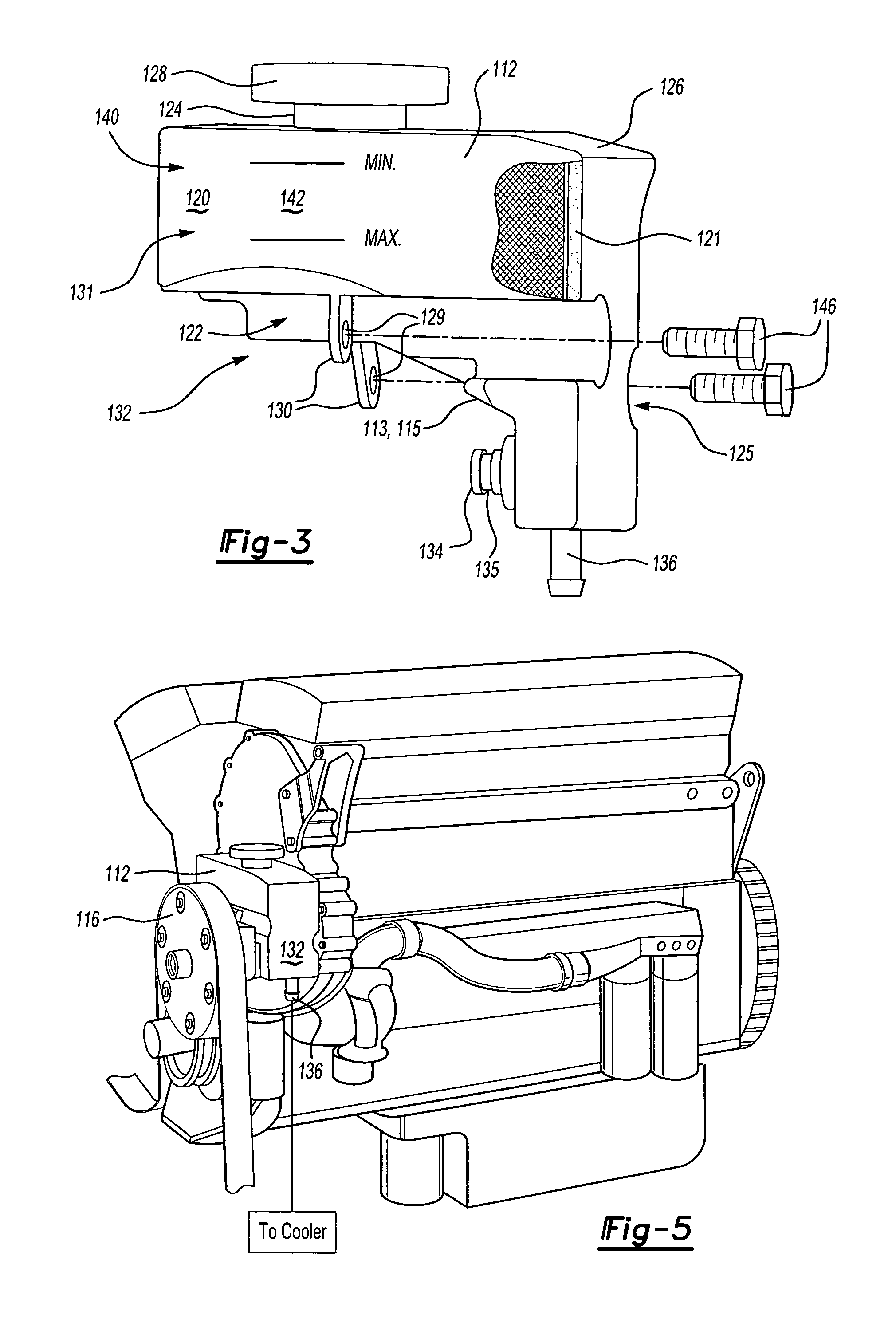
[0021]Referring to FIG. 1, a prior art power assist system 10 is schematically shown comprising a pump 12 for supplying a motor vehicle subsystem 14 with fluid 15 using a high pressure line 16. Pump 12 may be a variable displacement or a positive fixed hydraulic pump such as a power steering pump, oil pump, transmission pump, etc. A return line 20 transfers fluid 15 between the motor vehicle subsystem 14 and a reservoir 22. An optional cooler 18 is often found in such systems to reduce the temperature of the fluid 15 exiting the motor vehicle subsystem 14 and prior to returning to the reservoir 22. The reservoir 22 is typically secured to a first vehicle component support structure 24 such as a vehicle body, frame or a portion of an engine using reservoir fasteners 25. The reservoir fasteners 25 may be bolts, such as hex head carriage bolts, screws, or any other conventional fastener. Supply line 26 provides fluid 15 returned or stored in the reservoir 22 to pump 12. The supply line...


PUM


Abstract

A power assist system for a motor vehicle subsystem having a component support structure is described. The power assist system comprises a fluid reservoir, a pump having an inlet for receiving a fluid from the reservoir and a pump securing structure including at least one aperture. The system additionally includes at least one fastener. The reservoir fluid outlet is directly coupled to the pump inlet and the at least one fastener secures the reservoir mounting structure by passing directly through the pump mounting structure and attaching to the motor vehicle component support structure.

Description

BACKGROUND OF THE INVENTION[0001]1. Field of the Invention[0002]The present invention relates to a fluid power assist system for a motor vehicle. More specifically, this invention relates to a fluid power assist system having a fluid reservoir in cooperation with a pump for a motor vehicle.[0003]2. Prior Art[0004]Conventional vehicles employ power assistance systems in many ways. Power assisted brakes and power assisted steering are just two of such applications. Power assisted steering systems are systems in which the steering force is produced by the driver's muscular energy and by an energy source within the vehicle. For this purpose, a hydraulic oil, which is pressurized by means of a pump and serves to generate or increase the steering power, is provided in a closed system. Power assisted brakes work in a similar manner. The energy source may comprise a vacuum booster for a brake system or a pump driven by flywheel for a steering system. These systems typically include an oil r...

Claims


Application Information

Patent Timeline
Patent Type & Authority Patents(United States)
IPC IPC(8): F04B35/00B60K17/28
CPCB62D5/063Y10T137/0402Y10T137/85978
Inventor KAMMAN, KENNETH
Owner FORD GLOBAL TECH LLC
Why Eureka
Try Eureka