Electrical plug connector

a technology of electrical plugs and connectors, applied in the direction of coupling contact members, coupling device connections, contact members penetrating/cutting insulation/cable strands, etc., to achieve the effect of positive effect on tolerances relating to transmission response and limited joint flexing

Inactive Publication Date: 2006-01-05
COMMSCOPE TECH LLC
View PDF14 Cites 7 Cited by
  • Summary
  • Abstract
  • Description
  • Claims
  • Application Information

AI Technical Summary

Benefits of technology

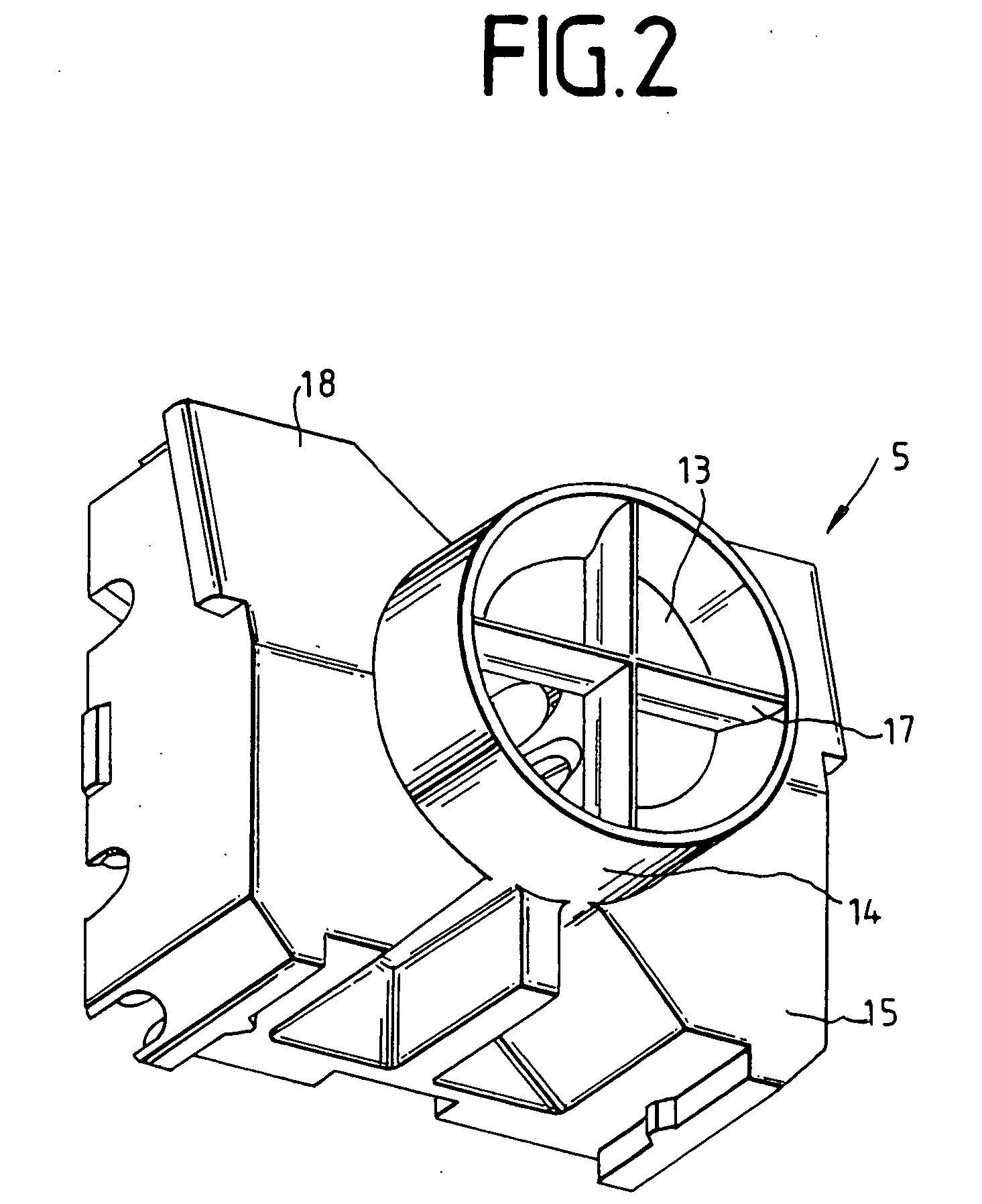
[0004] To this end, the plug connector comprises a cable manager which has a through-opening and is formed on the front face with guides for cores which are intended to make contact with the insulation-displacement contacts, in which case the guides in the region of the insulation-displacement contacts are formed with recessed holders for the insulation-displacement contacts, and the cable manager can be latched to the plug connector housing. This results in a number of major advantages in comparison to the prior art, which restrict the transmission response tolerances. The guides fix the length of the cores with which contact is to be made, in a defined manner. For this purpose, the respective core is passed through the openings and is inserted into the guides. Projecting parts of the core are then cut off at the edge of the cable manager, so that the length of the cores is the same in each plug connector. Furthermore, the guides mean that the cores can each all be located in a reproducible position with respect to one another. These two facts result in a fixed value for the crosstalk. A further advantage is that, once the cores have been fitted in the cable manager, contact between them and the insulation-displacement contacts can be made simultaneously, or virtually simultaneously.
[0011] In a further preferred embodiment, the guides are at offset levels in either direction with respect to one another, so that some of the cores make contact with one another at different times. This also results in the necessary contact forces being distributed better, so that the user requires less force for assembly and connection.
[0014] To this end, the tool or the first part of the cable grip comprises two jaw parts which are located together and whose joint flexing can be limited by means of a spring which engages around the jaw parts and can be inserted at different points on the first part. A force-fitting connection to the cable can be produced by means of a third part, which can be latched to the first part and / or to the spring. In addition to the force-fitting connection, this multipart cable grip also allows cables of different diameter to be centered, which in turn has a positive effect on the tolerances relating to the transmission response.

Problems solved by technology

A further technical problem is the provision of a method for assembly of an electrical plug connector and of a tool for assembly of the plug connector, and for the connection of the cores of the electrical plug connector.

Method used


Image

  • Electrical plug connector
  • Electrical plug connector
  • Electrical plug connector

Examples


Embodiment Construction

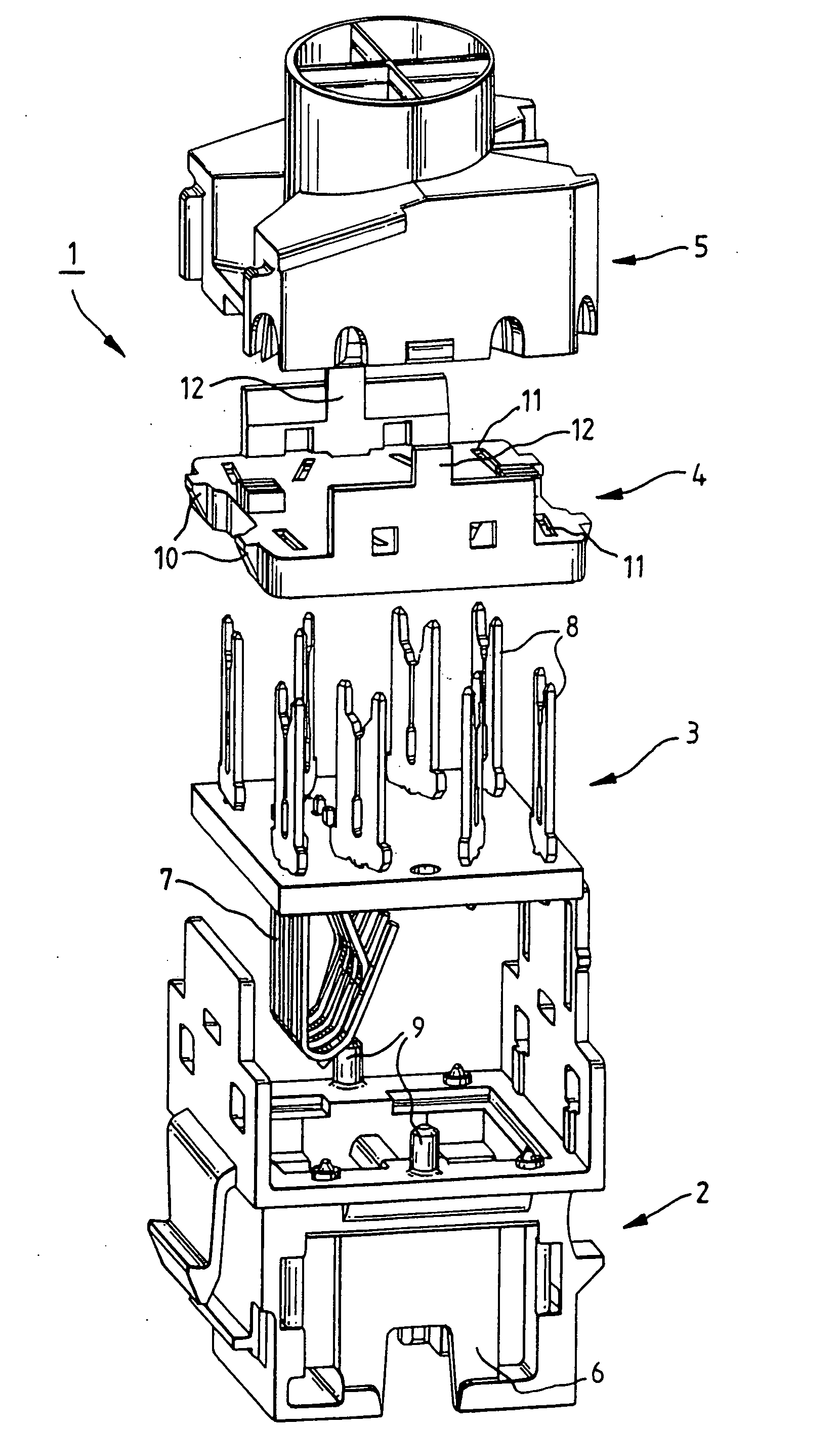
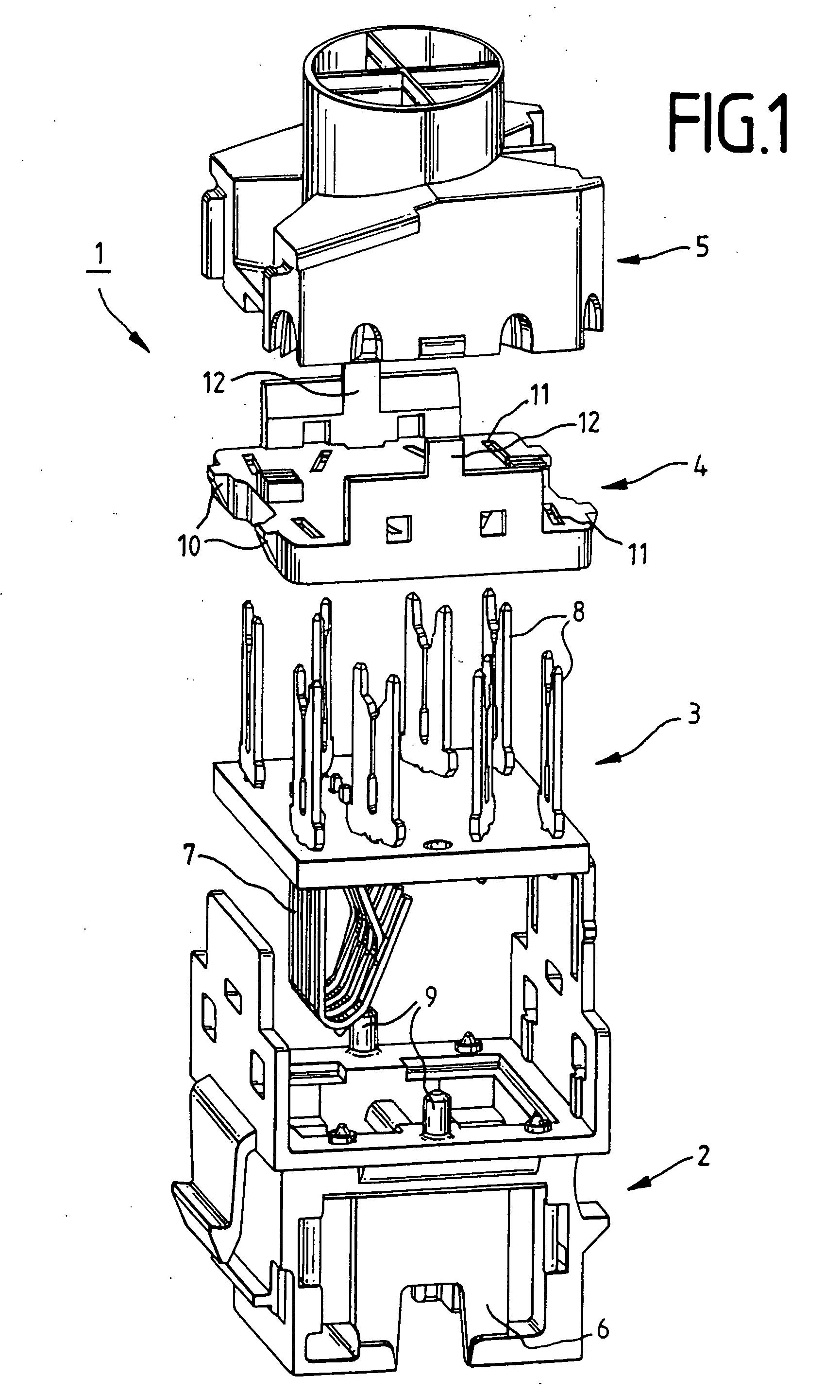
[0029] Referring to the drawings in particular, FIG. 1 shows an exploded illustration of a plug connector 1. The plug connector 1 comprises a plug connector housing 2, a printed circuit board 3, a hold-down device 4 and a cable manager 5. The plug connector housing 2 in the illustrated example is in the form of a socket housing with various latching and insertion means. The plug connector housing 2 is designed with a shielding plate 6 on the side surfaces. The printed circuit board 3 is fitted with a first set of contacts 7 on its front face and with a second set of insulation-displacement contacts 8 on its rear face. One contact 7 in the first set is in each case connected to one contact 8 in the second set. The printed circuit board 3 is then inserted into the plug connector housing 2. In the process, cylindrical pins 9 on the plug connector housing 2 pass through holes in the printed circuit board 3, so that the plug connector housing 2 and printed circuit board 3 can be adjusted...


PUM


Abstract

An electrical connector includes a connector housing (2) and a printed circuit board (3) with two sets of contact elements (7, 8). The first set of contact elements (7) is located on the front face of the printed circuit board (3) and protrudes into an opening in the plug connector housing (2). The second set of contact elements (8) is located on the rear face of the printed circuit board (3). The contact elements of the second set (8) are configured to form insulation-displacement contacts (8). The plug connector (1) also includes a cable manager (5) which has a continuous opening (13) and is configured on the front face (16) with guides (19) for cores or wires which are intended to make contact with the insulation-displacement contacts (8). The guides (19) in the region of the insulation-displacement contacts (8) are configured with recessed receiving elements or holders (20) for the insulation-displacement contacts (8), and the cable manager (5) can be latched to the plug connector housing (2).

Description

FIELD OF THE INVENTION [0001] The invention relates to an electrical plug connector, a cable manager for an electrical plug connector, a method for assembly of an electrical plug connector, and a tool for assembly and connection of the cores of the electrical plug connector. BACKGROUND OF THE INVENTION [0002] EP 0 445 376 131 discloses a plug connector for connecting a plug to electrically insulated conductors, having a housing which has a cavity to accommodate the plug, and with a first and a second set of connecting elements being provided. Each connecting element in the first set has an insulation-displacement contact for holding an insulated conductor and for making a contact connection with its core, and has a foot section. Each connecting element in the second set has a contact strip and a contact tongue, with each of the connecting elements in the second set being electrically connected via the contact tongue to the foot section of the connecting elements in the first set and...

Claims


Application Information

Patent Timeline
Patent Type & Authority Applications(United States)
IPC IPC(8): H01R4/24H01R9/03H01R13/58H01R13/14H01R13/514H01R24/58H01R43/00H01R43/22
CPCH01R4/2433H01R9/031H01R13/582H01R13/5837H01R24/64H01R13/6599H01R4/2429H01R9/2416H01R4/2445H01R13/5804H01R13/506H01R24/58
Inventor MOSSNER, FRANKNAD, FERENCGWIAZDOWSKI, MICHAEL
Owner COMMSCOPE TECH LLC
Why Eureka
Try Eureka