

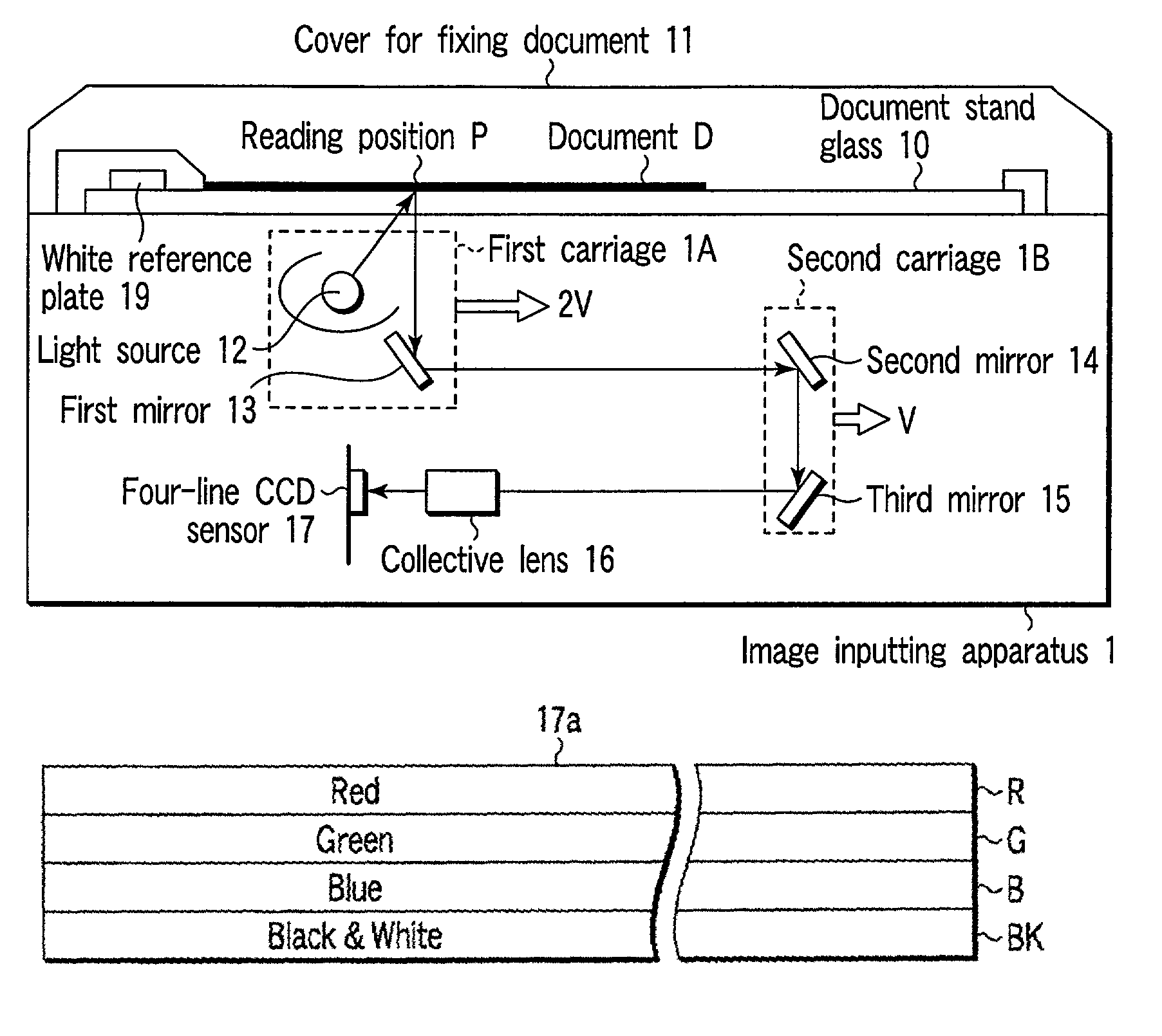
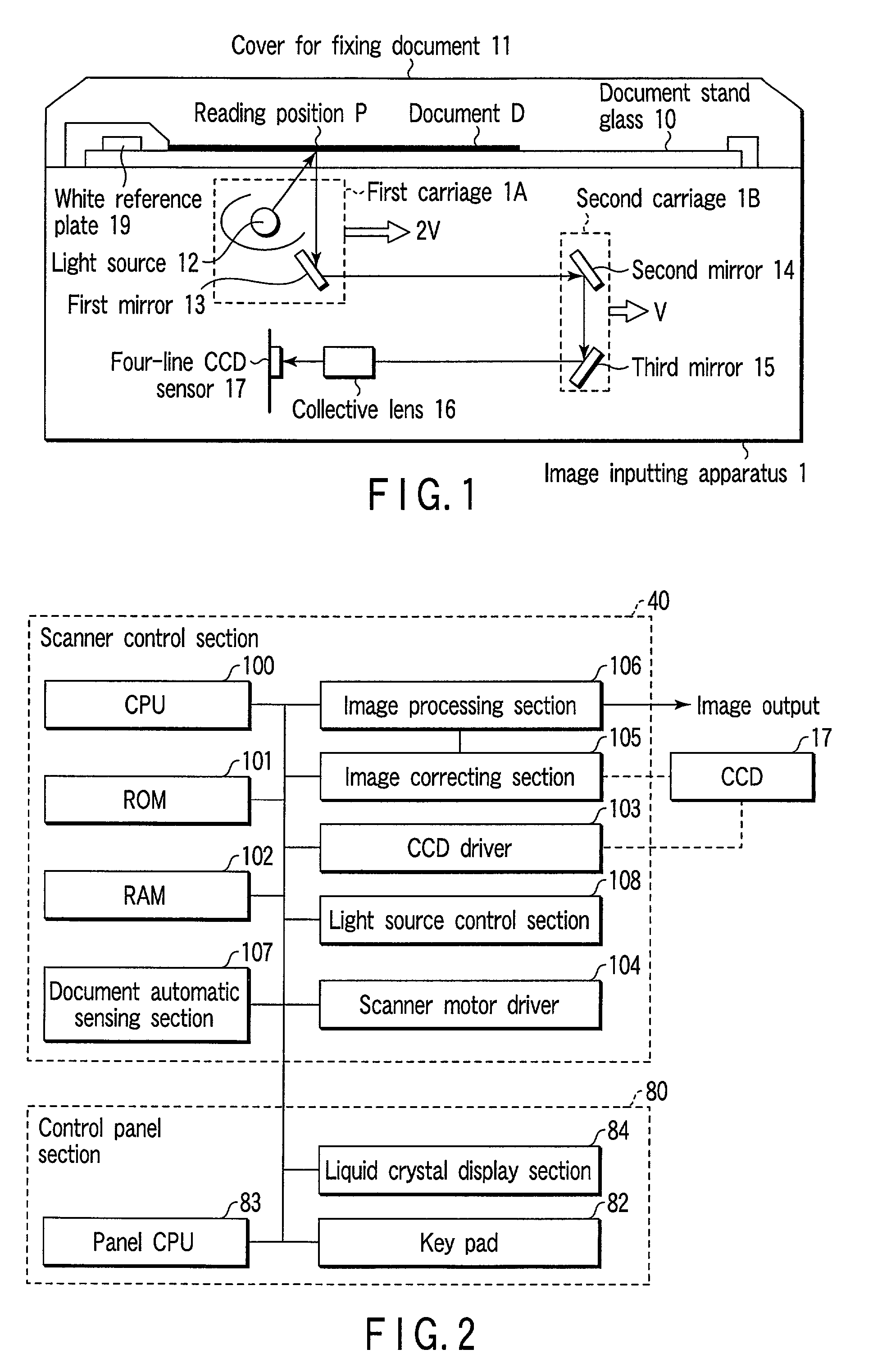
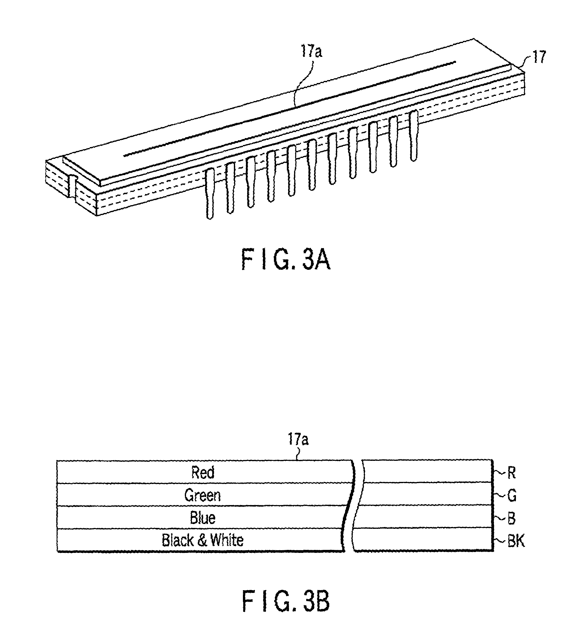
Image inputting apparatus and image forming apparatus using four-line CCD sensor
a technology of image input and forming apparatus, which is applied in the direction of electrical equipment, pictoral communication, etc., can solve the problems of inability to read information of green characters or images or the like, complicated control of light source relationships, and increased costs
- Summary
- Abstract
- Description
- Claims
- Application Information
AI Technical Summary
Benefits of technology
Problems solved by technology
Method used
Image

Examples
first embodiment
[0073]the present invention will be described hereinafter.
[0074]The sensitivity of a CCD line sensor is defined by using the illuminance which is incident per unit time as shown by [V / (lx·sec)]. Therefore, the light accumulating time of one line is changed at the time of using the line sensor BK, and at the time of using the line sensors R, G, B. This will be described specifically by using FIG. 9.
[0075]The SH signal and the transfer CLK 1, 2 which are shown in FIG. 9A are the same as the signals which are shown in FIG. 8. The SH signal is a signal which operates the shift gate at the inner portion of the four-line CCD sensor 17, and the transfer CLK 1, 2 are signals which carry out the control of the analog shift register. In a case in which image information is read by using the line sensor BK, as described above, if the frequency of the transfer CLK is 20 MHz, the light accumulating time tINT(BK) of one line is 400 μs.
[0076]Next, in a case in which image information is read by us...
second embodiment
[0082]Next, the present invention will be described. The characterizing feature of this embodiment is that the light amount control of the light source is carried out in accordance with the type of the line sensor which is used. FIG. 11 is a flowchart showing the operation of the present embodiment. For example, when the monochrome document D is read by the line sensor BK, the CPU 100 uses the light source control section 108 to lower the light amount and light the light source 12 (step S12). When the color document D is read by the line sensors R, G, B, the CPU 100 uses the light source control section 108 to light the light source 12 at the rating (step S13). In this case, the light amount of the light source may be controlled such that the signal amplitude outputted from the line sensor BK coincides with the signal having the largest amplitude among the output signals of the line sensors R, G, B.
[0083]Due to this control, the intensity of the reflected light from the document D c...
third embodiment
[0084]Next, the present invention will be described. The structure relating to the present embodiment is shown in FIG. 12. In this embodiment, as shown in FIG. 12A, the characterizing features are that two light sources 12A, 12B are provided, and a light source which emits light is controlled in accordance with the type of the line sensor. FIG. 13 is a flowchart showing the operation of the present embodiment.
[0085]When the monochrome document D is read by using the line sensor BK, as shown in FIG. 12B, the CPU 100 lights the light source 12A among two light sources, and turns off the light source 12B (step S22). Further, when the color document D is read by the line sensors R, G, B, the CPU 100 carries out the control to light both of the light source 12A and the light source 12B as shown in FIG. 12C (step S23). In this way, the intensity of the reflected light from the document can substantially the same at the line sensor BK and at the line sensors R, G, B when the same white por...
PUM
 Abstract
Description
Claims
Application Information