
Image inputting apparatus and image forming apparatus using four-line CCD sensor

a technology of image input and forming apparatus, which is applied in the direction of electrical equipment, pictoral communication, etc., can solve the problems of inability to read information of green characters or images or the like, complicated control of light source relationships, and increased costs

Active Publication Date: 2011-09-27
KK TOSHIBA +1
View PDF26 Cites 2 Cited by
  • Summary
  • Abstract
  • Description
  • Claims
  • Application Information

AI Technical Summary

Benefits of technology

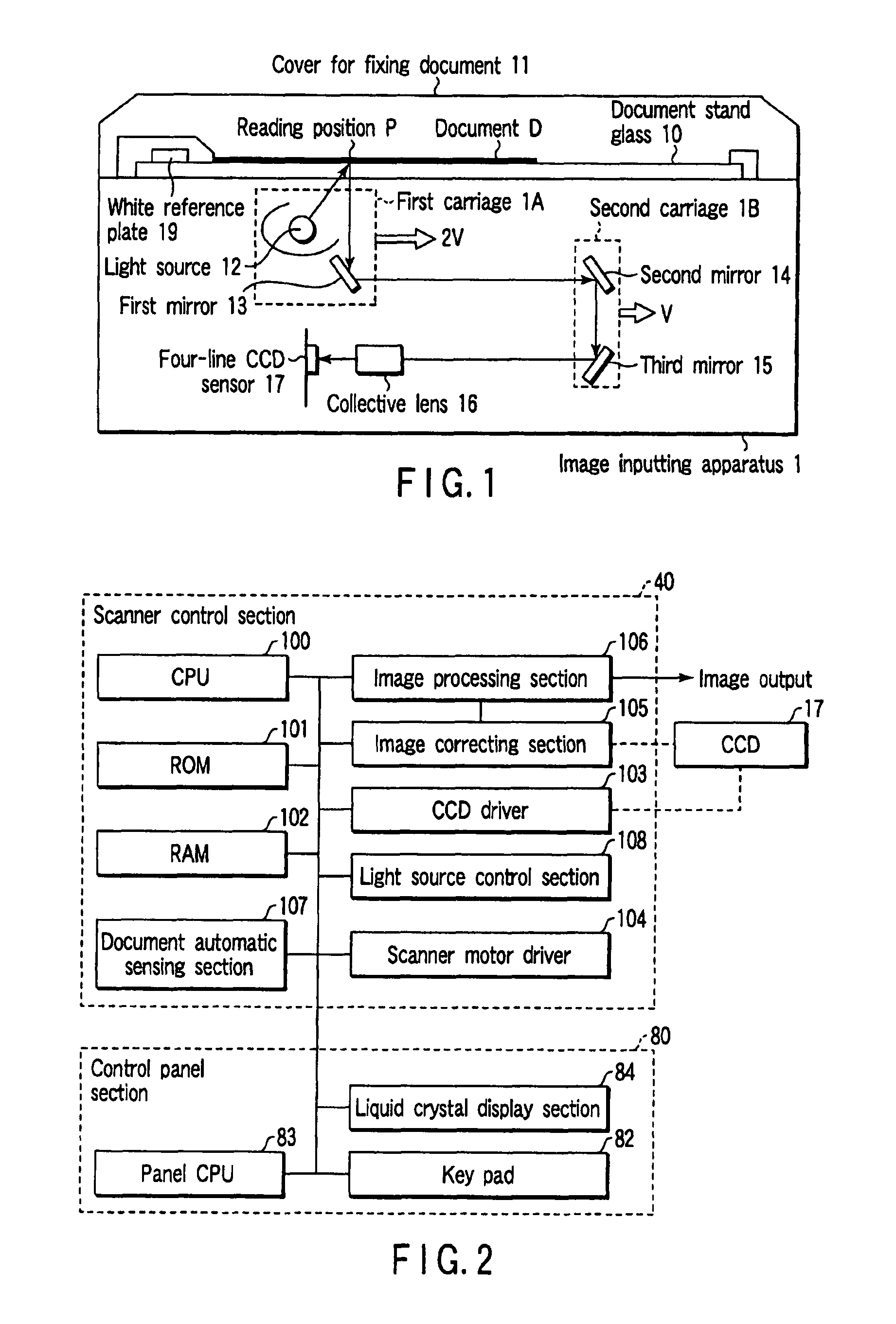
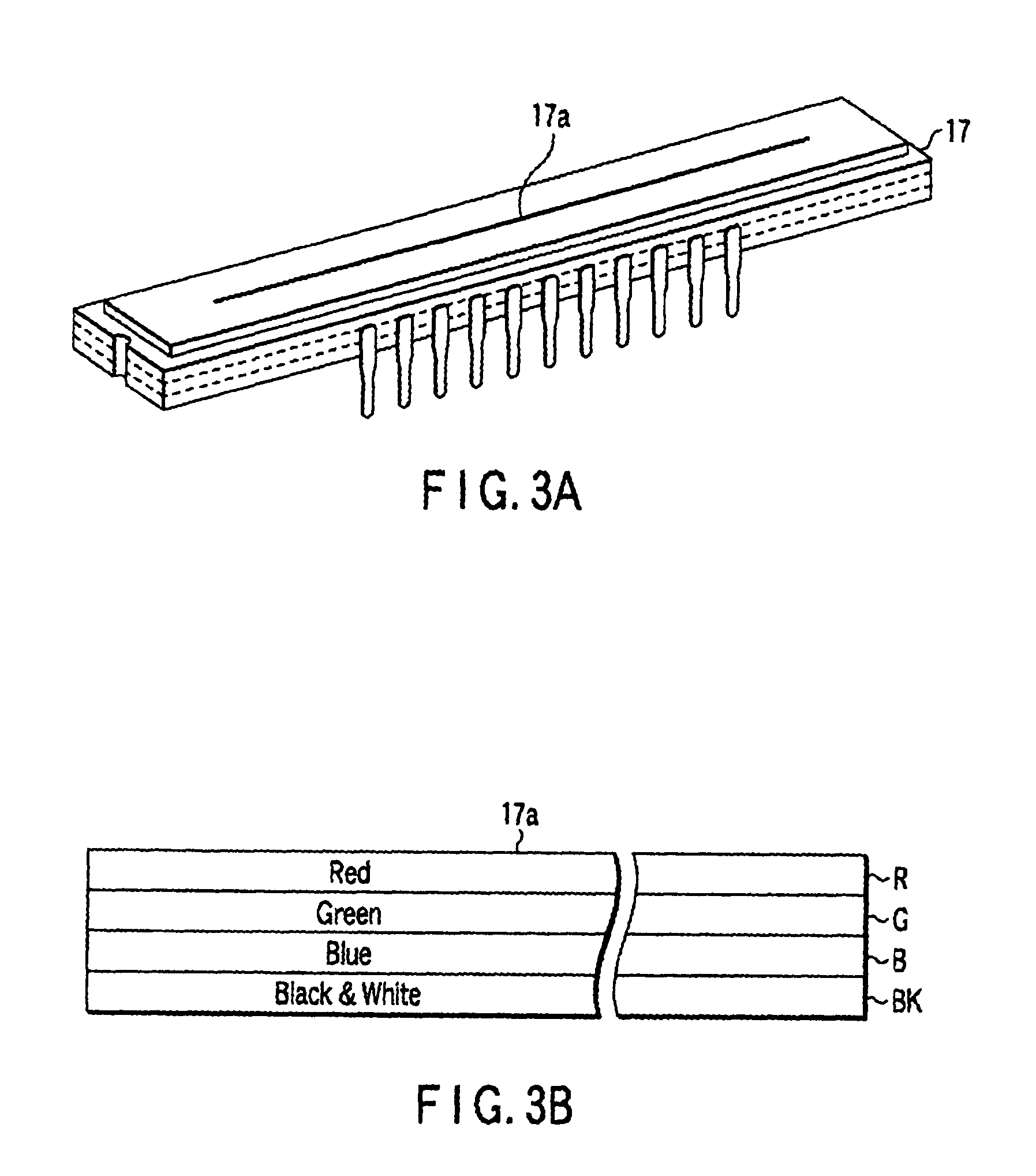
The present invention provides an image inputting apparatus and an image forming apparatus that can read color information of a document without causing positional offset and false colors when reading a monochrome document. This is achieved by using a four-line CCD sensor with different sensitivities for different line sensors. The image inputting apparatus has two light sources to control the illuminance of the document surface and uses gain amplifiers with different amplification factors for different line sensors. The apparatus can automatically detect the type of document being read and switch between color and monochrome modes accordingly.

Problems solved by technology

Thus, there are disadvantages in that the control of the light source relationships is complicated, and costs accompanying such control increase.
However, the green color information and the white information on the document cannot be distinguished from one another, and as a result, information of green characters or images or the like cannot be read.
In the same way, in a case in which the line sensor having sensitivity of R is used, a drawback arises in that the red information cannot be read, and in a case in which the line sensor having sensitivity of B is used, a drawback arises in that the blue information cannot be read.
However, because the one-line reading range in the subscanning direction varies in accordance with the reading magnification, there is the problem that the above-described proportional relationship is not established, and the alignment of color information by the line buffers is poor.
Moreover, in a case in which an image is rapidly changed from white to black or from black to white such as a monochrome characters, the drawback that false colors such as red or blue are generated at the changing points arises.

Method used


Image

  • Image inputting apparatus and image forming apparatus using four-line CCD sensor
  • Image inputting apparatus and image forming apparatus using four-line CCD sensor
  • Image inputting apparatus and image forming apparatus using four-line CCD sensor

Examples


first embodiment

[0073]the present invention will be described hereinafter.

[0074]The sensitivity of a CCD line sensor is defined by using the illuminance which is incident per unit time as shown by [V / (1x·sec)]. Therefore, the light accumulating time of one line is changed at the time of using the line sensor BK, and at the time of using the line sensors R, G, B. This will be described specifically by using FIG. 9.

[0075]The SH signal and the transfer CLK 1, 2 which are shown in FIG. 9A are the same as the signals which are shown in FIG. 8. The SH signal is a signal which operates the shift gate at the inner portion of the four-line CCD sensor 17, and the transfer CLK 1, 2 are signals which carry out the control of the analog shift register. In a case in which image information is read by using the line sensor BK, as described above, if the frequency of the transfer CLK is 20 MHz, the light accumulating time tINT(BK) of one line is 400 μs.

[0076]Next, in a case in which image information is read by us...

second embodiment

[0082]Next, the present invention will be described. The characterizing feature of this embodiment is that the light amount control of the light source is carried out in accordance with the type of the line sensor which is used. FIG. 11 is a flowchart showing the operation of the present embodiment. For example, when the monochrome document D is read by the line sensor BK, the CPU 100 uses the light source control section 108 to lower the light amount and light the light source 12 (step S12). When the color document D is read by the line sensors R, G, B, the CPU 100 uses the light source control section 108 to light the light source 12 at the rating (step S13). In this case, the light amount of the light source may be controlled such that the signal amplitude outputted from the line sensor BK coincides with the signal having the largest amplitude among the output signals of the line sensors R, G, B.

[0083]Due to this control, the intensity of the reflected light from the document D c...

third embodiment

[0084]Next, the present invention will be described. The structure relating to the present embodiment is shown in FIG. 12. In this embodiment, as shown in FIG. 12A, the characterizing features are that two light sources 12A, 12B are provided, and a light source which emits light is controlled in accordance with the type of the line sensor. FIG. 13 is a flowchart showing the operation of the present embodiment.

[0085]When the monochrome document D is read by using the line sensor BK, as shown in FIG. 12B, the CPU 100 lights the light source 12A among two light sources, and turns off the light source 12B (step S22). Further, when the color document D is read by the line sensors R, G, B, the CPU 100 carries out the control to light both of the light source 12A and the light source 12B as shown in FIG. 12C (step S23). In this way, the intensity of the reflected light from the document can substantially the same at the line sensor BK and at the line sensors R, G, B when the same white por...


PUM


Abstract

A four-line CCD sensor is structured by line sensors R, G, B in which color filters are respectively disposed on surfaces of light receiving elements, and a line sensor BK at which no color filter is disposed. Amplitudes of signals which are outputted from the line sensors R, G, B at a time of reading a color document, and an amplitude of a signal which is outputted from the line sensor BK at a time of reading a monochrome document are adjusted so as to be substantially equal to one another. In a case in which a color document is read, outputs of the line sensors R, G, B are selectively provided, and in a case in which a monochrome document is read, output of the line sensor BK is selectively provided.

Description

BACKGROUND OF THE INVENTION[0001]The present invention relates to an image inputting apparatus such as a scanner or the like which reads image information by scanning a document, and to an image forming apparatus such as a digital copier or the like which uses the image inputting apparatus.[0002]Conventionally, there are generally two types of CCD line sensors which are used in a reduction optical system: a CCD line sensor which is structured by only a one-line line sensor, and a CCD line sensor which is structured by a three-line line sensor in which color filters of red (hereinafter denoted as R), green (hereinafter denoted as G), and blue (hereinafter denoted as B) are disposed on the surfaces of the respective line sensors.[0003]The aforementioned one-line CCD line sensor is basically used for reading monochrome (white / black) documents. When a color document is read by using this CCD line sensor, a method is adopted in which, by successively turning on three light sources having...

Claims


Application Information

Patent Timeline
Patent Type & Authority Patents(United States)
IPC IPC(8): H04N1/46H04N1/407H04N1/48
CPCH04N1/407H04N1/486
Inventor SAKAKIBARA, JUNTANIMOTO, KOJI
Owner KK TOSHIBA
Learn More