Apparatus and method for circular vortex air flow material grinding

a technology of air flow and apparatus, applied in the field of material grinding, can solve the problems of limited space in landfills

Inactive Publication Date: 2005-12-06
POLIFKA RUTH
View PDF17 Cites 42 Cited by
  • Summary
  • Abstract
  • Description
  • Claims
  • Application Information

AI Technical Summary

Benefits of technology

[0010]The present invention also is directed to a material grinding method which comprises the steps of: (a) providing an upper enclosure with at least one hole of a predetermined size formed therethrough between exterior and interior sides thereof and oriented so as to extend between and at an acute angle relative to the exterior and interior sides so as to provide flow communication between the exterior side thereof and an upper interior chamber thereof; (b) providing a lower enclosure below and in tandem with the upper enclosure and having an inverted conical configuration such that an lower interior chamber of the lower enclosure is substantially continuous and in flow communication with the upper interior chamber of the upper enclosure; (c) delivering material to be ground into the upper interior chamber of the upper enclosure through an upper end thereof; (d) supplying a flow of air, such as in a compressed state, through the hole in the upper enclosure into the upper interior chamber thereof to along a flow path extending about the interior side of the upper enclosure; and (e) exhausting air from the upper interior chamber of the upper enclosure through the upper end thereof such that the supplying of air and the exhausting of air coact with the hole in the upper enclosure and with the upper and interior chambers to create a circular vortex flow of air within the upper and lower interior chambers of the upper and lower enclosures that causes grinding and drying of material substantially in the upper interior chamber of the upper enclosure, downward travel of ground material through the lower interior chamber of the lower enclosure and downward discharge of the ground material from the lower interior chamber of the lower enclosure through an open lower end thereof, the lower interior chamber of the lower enclosure being provided with an inverted conical shape which augments the circular vortex flow of air and material in the upper and lower interior chambers of the upper and lower enclosures.

Problems solved by technology

Landfills often have limited space.
Problems exist with this arrangement in that the upper portion of the cyclone chamber is cylindrical shaped and separated from the grinding chamber so it does not augment a vortex air flow created in the grinding chamber.

Method used


Image

  • Apparatus and method for circular vortex air flow material grinding
  • Apparatus and method for circular vortex air flow material grinding
  • Apparatus and method for circular vortex air flow material grinding

Examples


Embodiment Construction

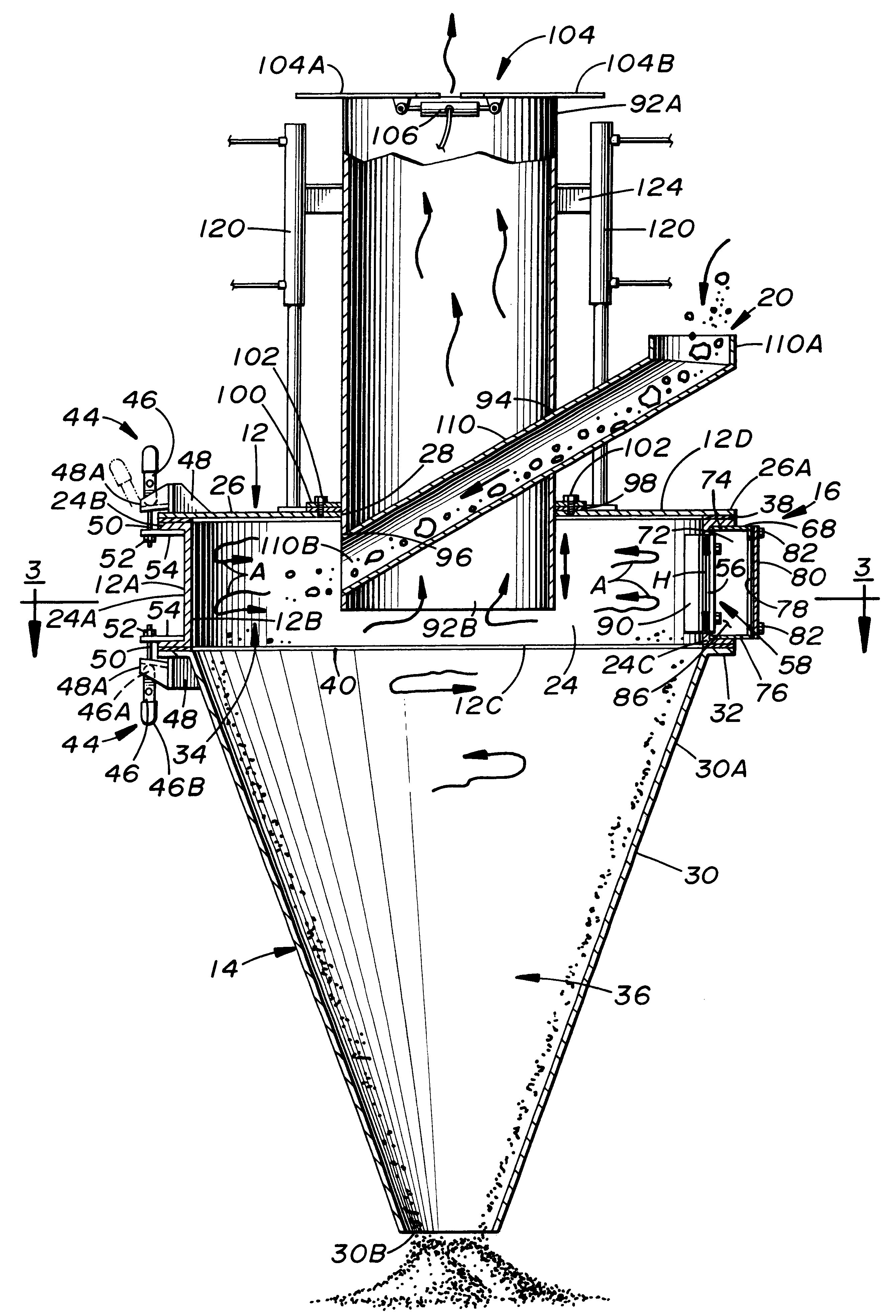
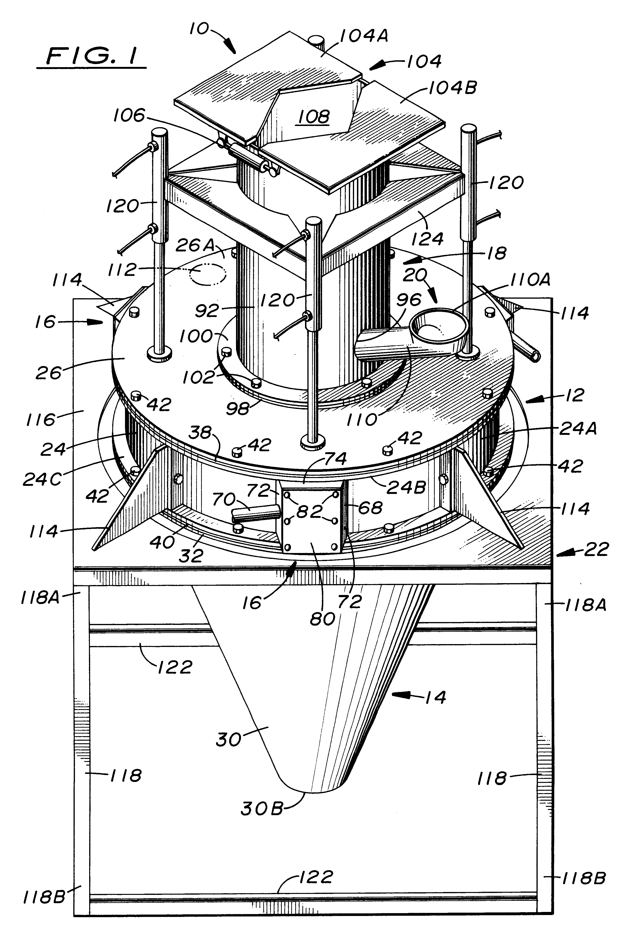
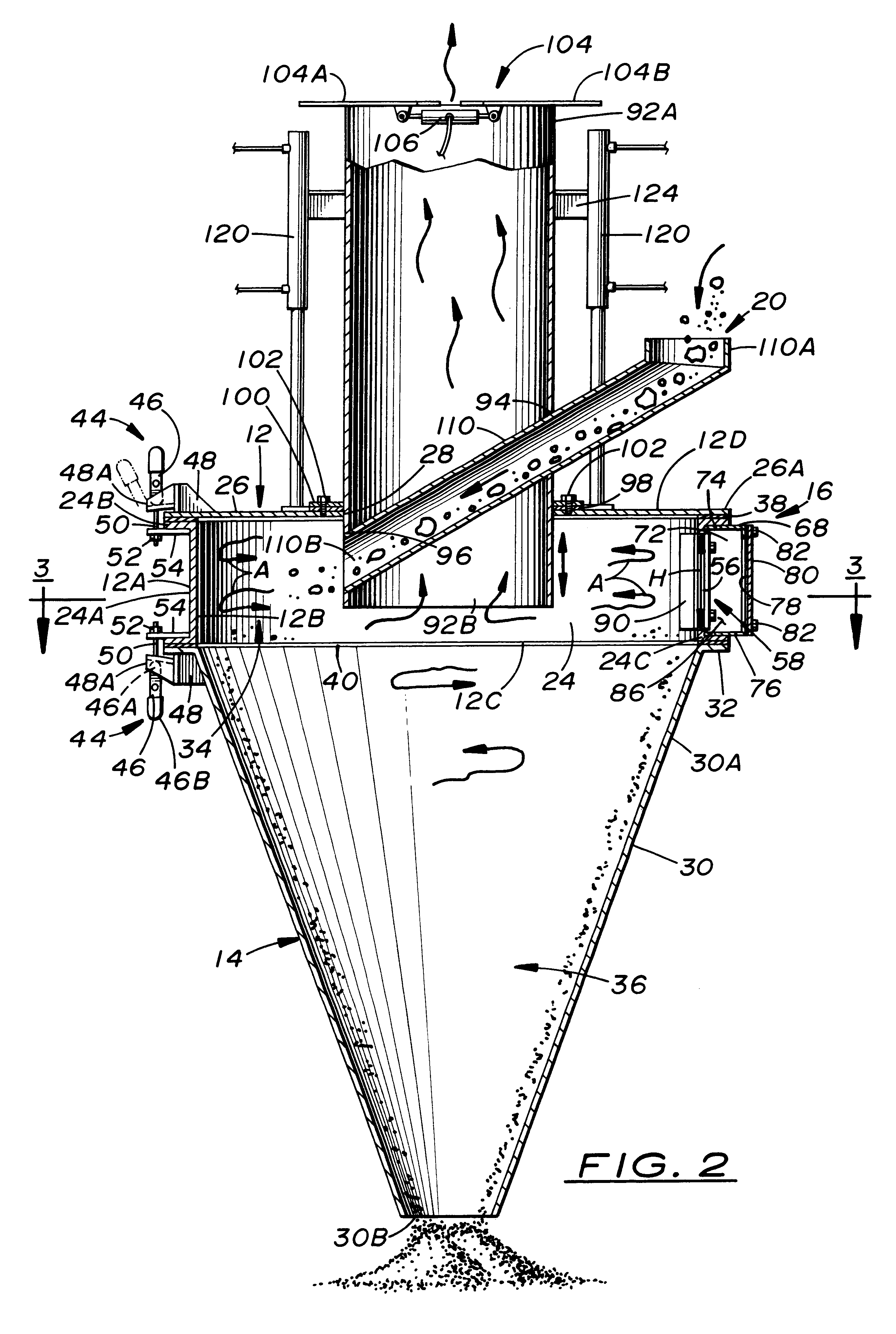
[0018]Referring to the drawings, and particularly to FIGS. 1 to 3, there is illustrated a material grinding apparatus, generally designated 10, of the present invention. The grinding apparatus 10 basically includes an upper enclosure 12, a lower enclosure 14, an air supplying means 16, an air exhausting means 18 and a material delivering means 20. The grinding apparatus 10 also includes a support structure 22 supporting the upper and lower enclosures 12, 14 in an upright tandem orientation.

[0019]Referring to FIGS. 1 to 5, the upper enclosure 12 includes a continuous upper annular sidewall 24 and has opposite exterior and interior sides 12A, 12B, an open lower end 12C and a closed upper end 12D. Its closed upper end 12D is provided preferably in the form of a top cover 26 removably mounted on and overlying the upper annular sidewall 24. The upper annular side wall 24 has a main annular wall portion 24A of substantially cylindrical configuration and upper and lower annular lip portion...


PUM


Abstract

A material grinding apparatus (10) includes an annular upper enclosure (12) defining an upper chamber (34) into which material to be ground is introduced from above, a conical lower enclosure (14) defining a lower chamber (36) and supported in tandem with the upper enclosure (12), and one or more angled slots (56) defined in the sidewall of the upper enclosure (12) through which compressed air is introduced relatively circumferentially into the upper chamber (34) so as to generate a circular vortex flow of air and material in the upper enclosure (12) for grinding and drying to take place. The air flow is exhausted by a pipe (92) through an upper end of the upper enclosure (12) and the dried ground material is discharged through an open lower end of the lower enclosure (14). The lower enclosure (14) is a downward continuation and extension of the upper enclosure (12) so as not to extend upwardly into nor past the upper chamber (34) thereof.

Description

[0001]This application claims the benefit of provisional application No. 60 / 125,570 filed Mar. 23, 1999.TECHNICAL FIELD[0002]The present invention generally relates to material grinding and, more particularly, is concerned with an apparatus and method for circular vortex air flow material grinding.BACKGROUND ART[0003]Landfills often have limited space. In order to reduce the volume of space which discarded materials occupy in landfills, it is generally desirable to have an apparatus capable of grinding diverse materials typically disposed of in landfills. Two approaches have employed air in the grinding process. One approach involves the use of a large volume of air which is generated by a fan. The other approach involves the use of air at high velocity instead of large volume. A variety of grinding devices using air have been developed over the years.[0004]Representative examples of such prior art grinding devices and the like are disclosed in U.S. Pat. No. 1,123,033 to Stobie, U.S...

Claims


Application Information

Patent Timeline
Patent Type & Authority Patents(United States)
IPC IPC(8): B02C19/06
CPCB02C19/061
Inventor POLIFKA, FRANCIS D.
Owner POLIFKA RUTH
Why Eureka
Try Eureka