Self loading LGA socket connector

a socket connector and self-loading technology, applied in the direction of coupling contact member, coupling device connection, coupling/disconnecting parts, etc., can solve the problems of contact lead fragility, damage to land, and beams susceptible to damage,

Inactive Publication Date: 2005-12-06
TE CONNECTIVITY CORP
View PDF12 Cites 97 Cited by
  • Summary
  • Abstract
  • Description
  • Claims
  • Application Information

AI Technical Summary

Problems solved by technology

These contact leads are somewhat fragile and can be damaged if not handled properly.
The land, however, could be scratched if the package was subjected to abuse.
This exposes the flexible surface mount contact beams, rendering the beams susceptible to damage during loading and unloading of the package.
The beams may be broken, bent, or otherwise deformed which results in misalignment of the beams with respect to the package.

Method used


Image

  • Self loading LGA socket connector
  • Self loading LGA socket connector
  • Self loading LGA socket connector

Examples


Embodiment Construction

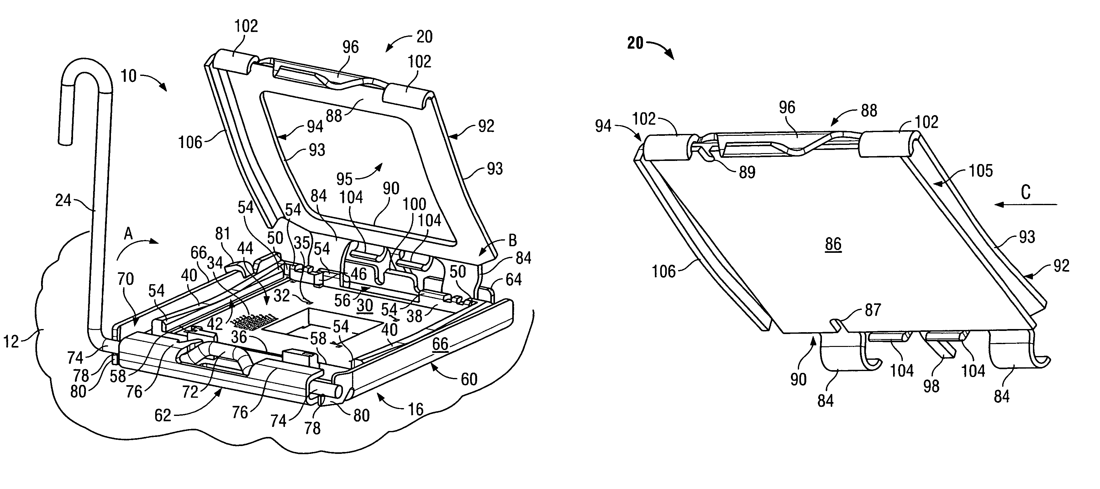
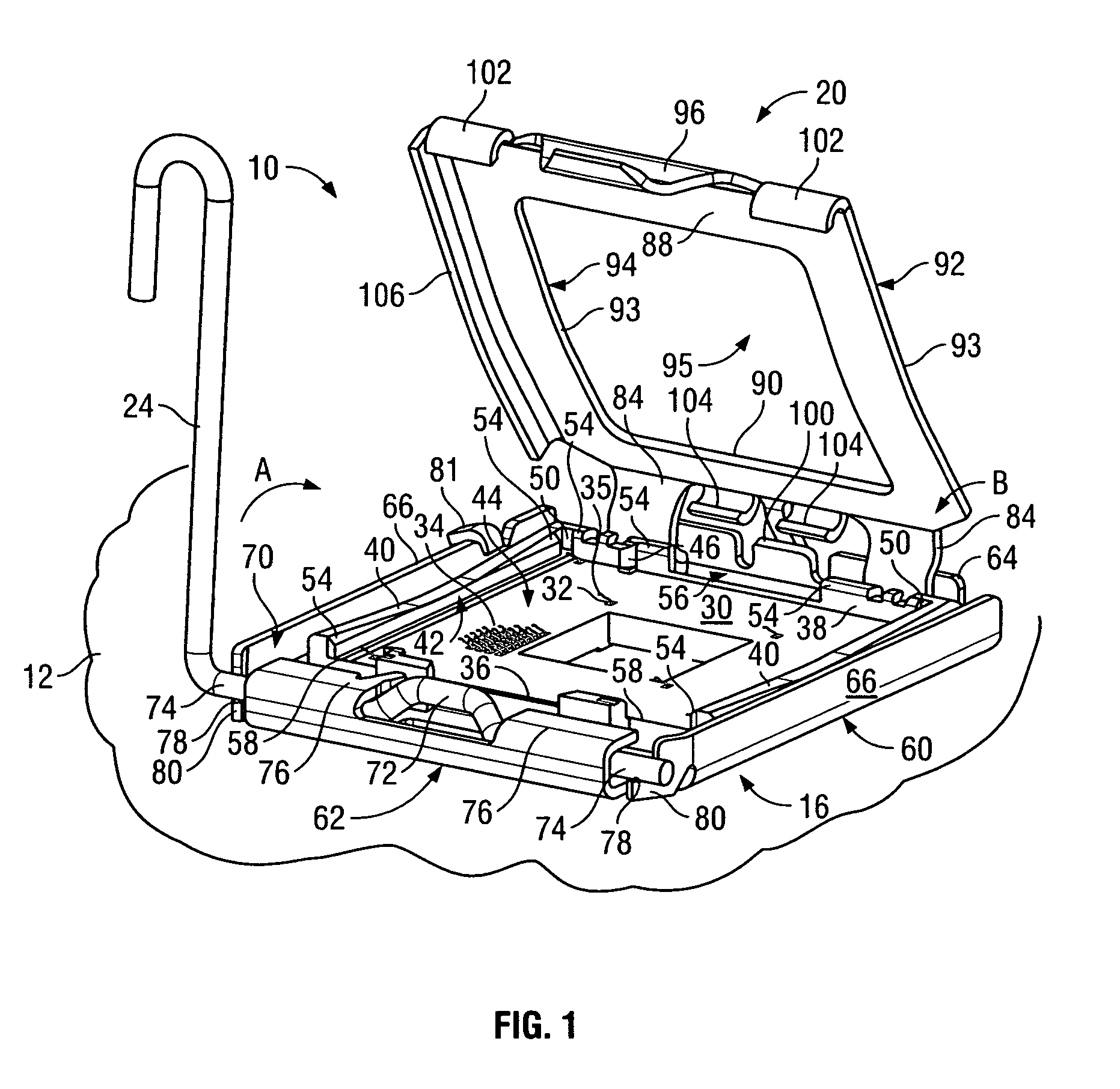
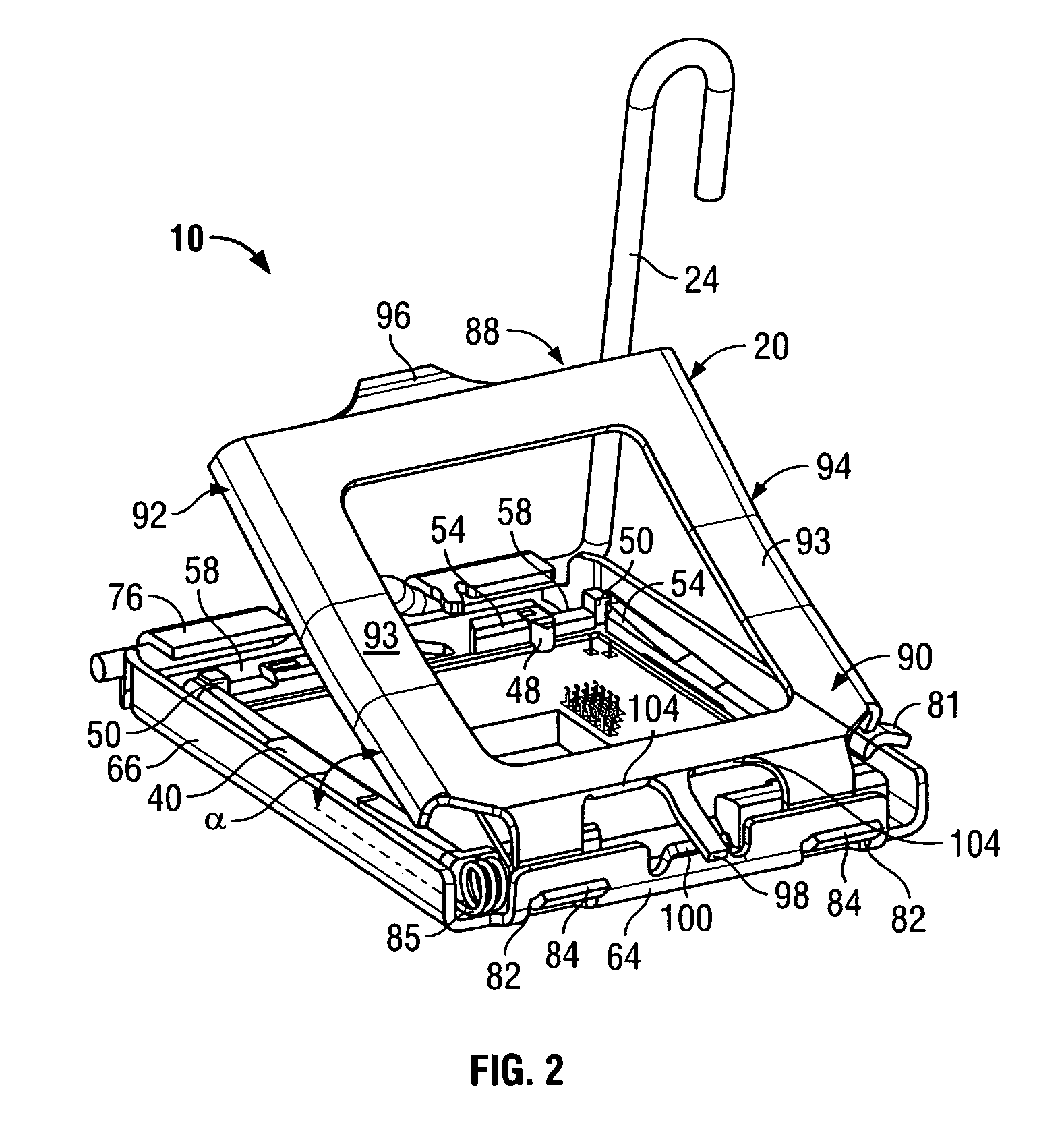
[0016]FIG. 1 is a front perspective view of an exemplary socket connector 10 formed in accordance with an exemplary embodiment of the present invention. FIG. 2 is a rear perspective view of the socket connect 10 shown in FIG. 1. While the connector 10 will be described with particular reference to a land grid array (LGA) module or package, it is to be understood that other electronic module types are not intended to be excluded.

[0017]The connector 10 is surface mounted to a circuit board 12 that may be used, among other applications, in a personal computer or in a server application. The connector 10 can be used to mount a central processing unit (CPU) or other chip carrying module to the circuit board 12. The connector 10 includes a socket housing 16 with a stiffener plate 60, a load plate 20, and a latch handle 24.

[0018]The housing 16 includes a base 30 which is fabricated from a dielectric material and includes an array of contact cavities 32 that hold an array 34 of individual e...


PUM


Abstract

An electrical connector is provided that includes a socket housing holding an array of electrical contacts and a load plate rotatably coupled to the housing and rotatable between an open position and a closed position. The load plate includes a channel that is configured to receive an electronic package when the load plate is in the open position. The load plate loads the package into the housing as the load plate is rotated to the closed position.

Description

BACKGROUND OF THE INVENTION[0001]The invention relates generally to area array socket connectors and particularly to a land grid array (LGA) socket connector.[0002]Competition and market demands have continued the trends toward faster, higher performance electrical systems, particularly with regard to computer systems. Along with the development of surface mount technology in the design of printed circuit boards, higher density electrical circuits, including higher density interconnect components have been developed to meet the increasing demand for higher performance electrical systems.[0003]As is well understood in the art, surface mountable packaging allows for the connection of the package to pads on the surface of the circuit board rather than by contacts or pins soldered in plated holes going through the circuit board. As used herein, the term “package” shall refer to a chip carrying module that is to be mounted to a circuit board. Surface mount technology allows for an increa...

Claims


Application Information

Patent Timeline
Patent Type & Authority Patents(United States)
IPC IPC(8): H01R4/50H01R13/24H01R13/625H01R13/627H01R13/629H01R13/631H01R13/639H01R33/76
CPCH01R13/2442H01R4/5066Y10S439/94
Inventor TAYLOR, ATTALEE S.SIPE, LYNN ROBERT
Owner TE CONNECTIVITY CORP
Why Eureka
Try Eureka