Beaded conveyor belt

a conveyor belt and beaded technology, applied in the field of conveyor belts, can solve the problems of cracking and/or breaking of the conveyor belt in a relatively short time period, and achieve the effect of preventing the inward shift of the belt body

Inactive Publication Date: 2005-12-13
NITTA CORP
View PDF21 Cites 50 Cited by
  • Summary
  • Abstract
  • Description
  • Claims
  • Application Information

AI Technical Summary

Benefits of technology

[0010]Furthermore, each of the bead composing elements may have a thick portion for preventing inward shift of the belt body by engaging with a bar guide member provided on the body of the conveyor.

Problems solved by technology

The occurrence of crack and / or breakage of the bead means destruction of the conveyor belt 90.
In a straight conveyor in which beads are sewed to both hem sides for prevention of meander of the belt, if the end roller has a small diameter, crack and / or breakage will occur in a relatively short time period.

Method used


Image

  • Beaded conveyor belt
  • Beaded conveyor belt
  • Beaded conveyor belt

Examples


Embodiment Construction

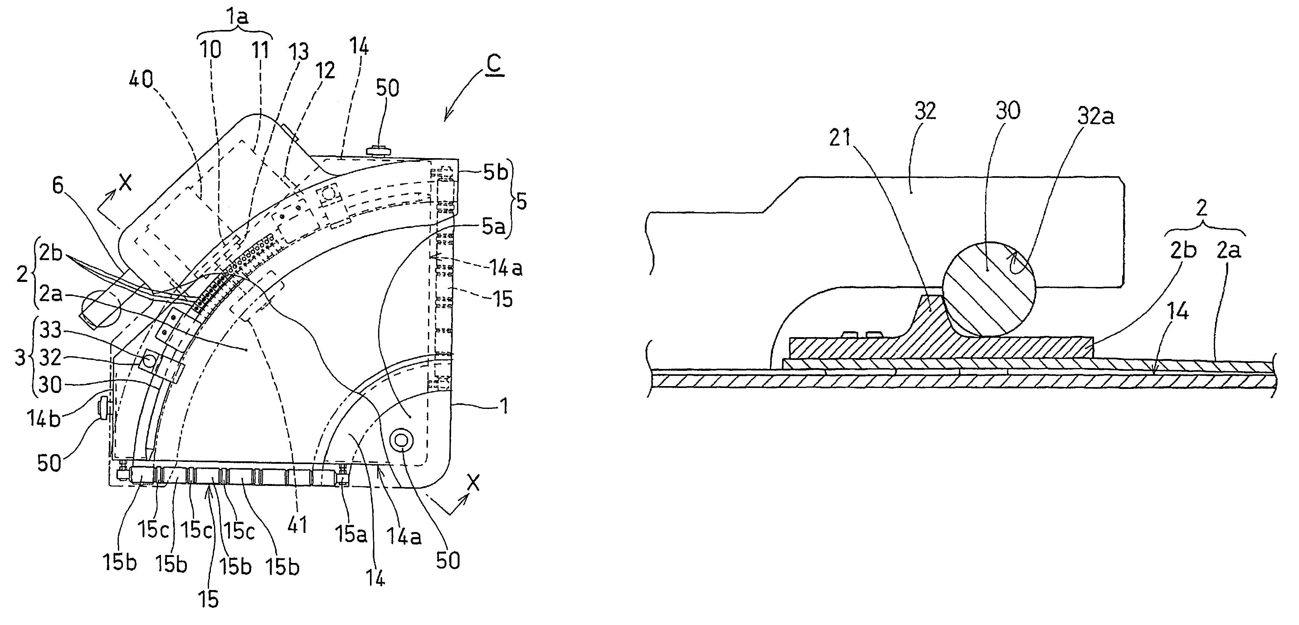
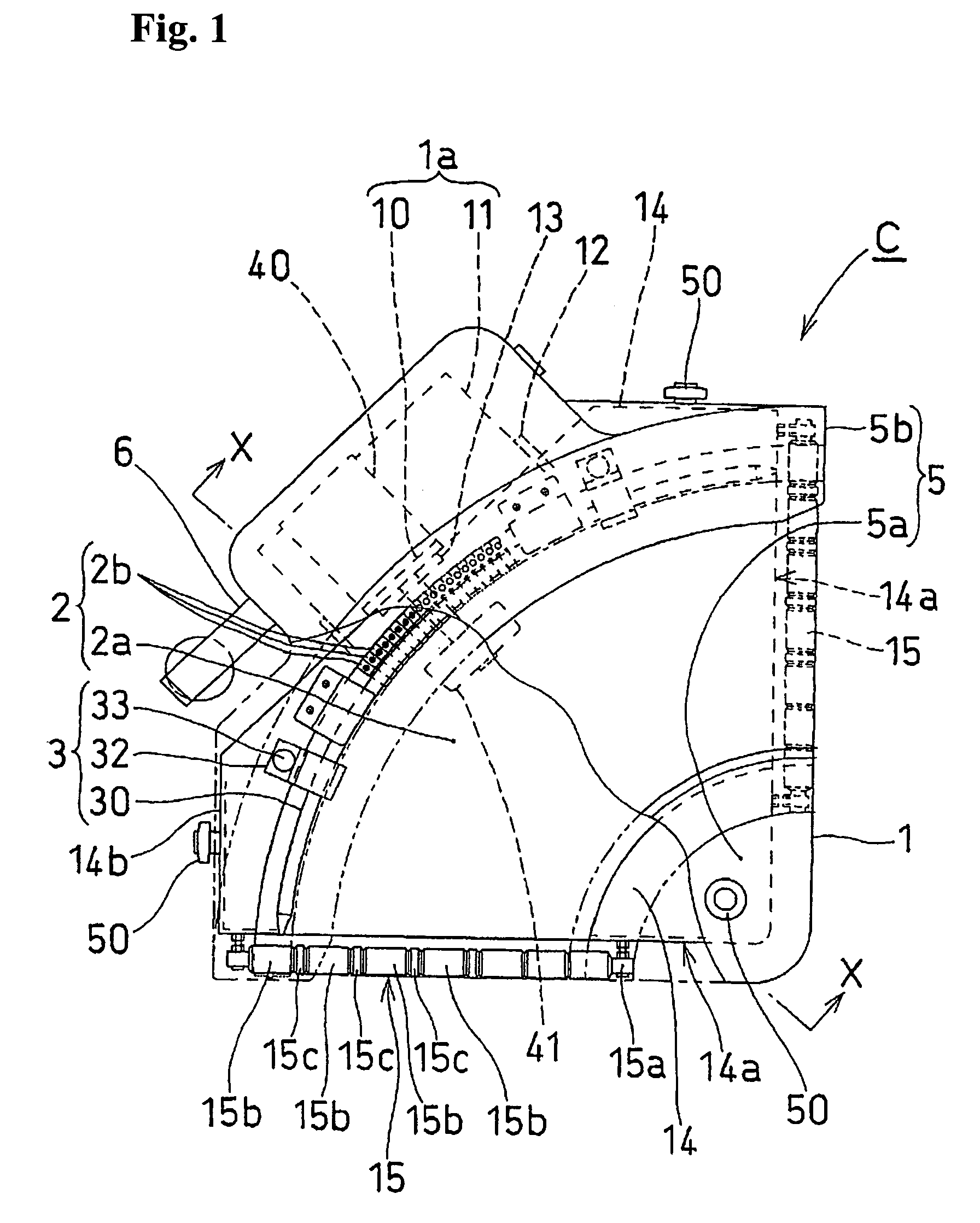
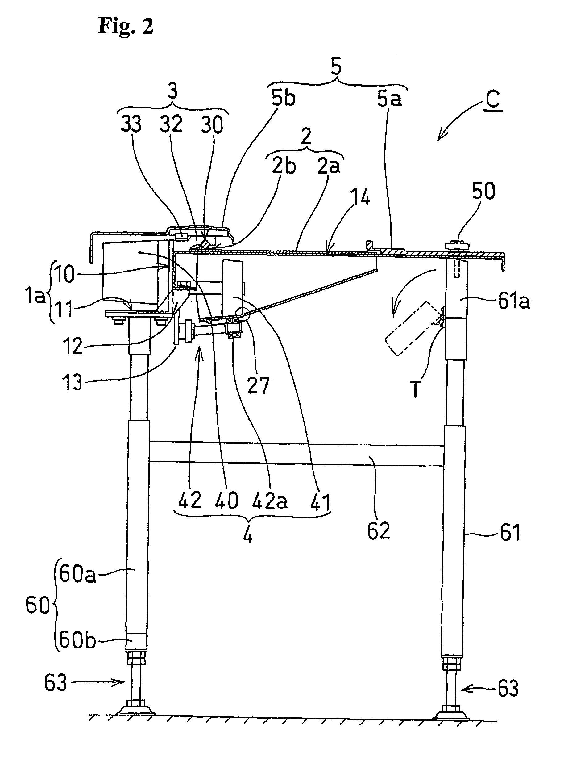
[0030]FIG. 1 shows a plan view of a conveyor C which employs a conveyor belt 2 with bead according to this invention. FIG. 2 is a sectional view taken along the line X—X in FIG. 1, and FIG. 3 is a bottom view of the conveyor C.

[0031]A basic constitution of this conveyor C is shown in FIGS. 1 to 3. The conveyor C includes a conveyor main body 1, a conveyor belt 2 with bead (hereinafter sometimes referred to as “beaded conveyor belt”) stretched on the conveyor main body 1, a shift prevention member 3 for preventing the beaded conveyor belt 2 from shifting inwardly, a driving member 4 for rotationally driving the beaded conveyor belt 2. The conveyor C also includes a cover member 5 which covers a motor 40 with a decelerator for the driving member 4, the shift prevention member 3 on the upper side and an inner and an outer peripheral portion of the beaded conveyor belt 2, and a leg member 6 which keeps the conveyor main body 1 at a suitable height. These main parts of the conveyor C wil...


PUM


Abstract

The beads of a beaded conveyor belt for a curve conveyor are constituted by a number of bead constituting bodies (2b) that are disposed over the entire periphery of the outer surface along the outer peripheral edge of a belt main body (2a) and that are narrow in the direction of the length of the belt. Further, the beads of a beaded conveyor belt for a liner conveyor are constituted by a number of bead constituting bodies (7b) that are disposed over the entire periphery of the outer surface along opposite side edge of a belt main body (7a) and that are narrow in the direction of the length of the belt. The conveyor belt is installed taut between straight type end rollers (15), and the width of the bead constituting bodies (2b, 7b) lengthwise of the belt is set at about 20–60% of the diameter of the straight type end rollers (15). Even when the conveyor belt is installed taut between small-diameter end rollers, long-term use is possible.

Description

FIELD OF THE INVENTION[0001]The present invention relates to a conveyor belt with bead used in a curved conveyor or a straight conveyor.PRIOR ART[0002]A curved conveyor, as illustrated in FIG. 14, is generally formed by stretching a conveyor belt 90 between end rollers 92 and 92 disposed rotatably at a certain angle and provided on a conveyor body 91. The conveyor belt 90 is shown in FIG. 15. A urethane rubber bead 93 is sewed together with the outer hem area. In order to prevent the inward shift due to the centripetal force during the rotation, the bead 93 is engaged with a guide members 94 attached to the conveyor body 91. The guide member of this type is generally disposed as shown in FIG. 15. A pair of bearings BR and BR is attached to a block B in a fashion that they are symmetrically inclined with respect of the horizontal plane. And a thick portion 93a of the bead 93 is held between the bearings BR and BR.[0003]During the rotation of this conveyor belt, the bead 93 is affecte...

Claims


Application Information

Patent Timeline
Patent Type & Authority Patents(United States)
IPC IPC(8): B65G15/02B65G15/46B65G21/16
CPCB65G15/02B65G15/46B65G2201/06
Inventor SAEKI, NAOYUKI
Owner NITTA CORP
Why Eureka
Try Eureka